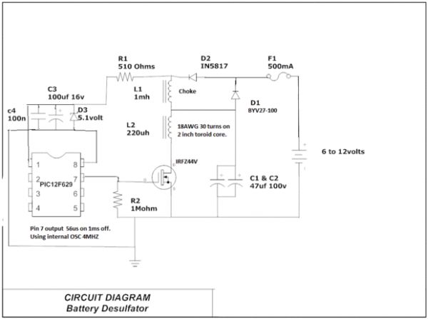
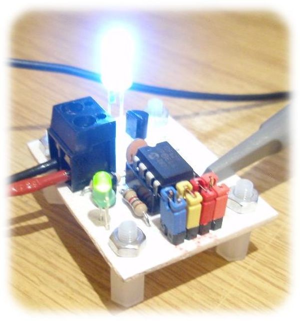
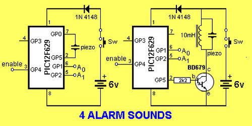
This project is a miniature 1-chip alarm. All you need is a tilt switch, battery and piezo to produce a complete alarm.
If you want a very high output, you can add a Darlington buffer transistor, piezo tweeter and a 10mH choke.
The chip does all the work.
It sits in sleep mode (100 microamps) and waits for the enable line to go high via the tilt switch.
It then produces a SPACE GUN alarm for approx 3 minutes and goes into sleep mode again.
The .asm and .hex for 4 Alarm Sounds chip with Space Gun selected when A0 and A1
HIGH, is in the following files:
4 Alarm Sounds.asm
4 Alarm Sounds.hex
Below is the program written by the original designer of the project. It is complex and contains an instruction: movlw wabl_dir_mask ;change direction This instruction is now allowed. Possibly it should be: movfw wabl_dir_mask ;change direction. I don’t know how he was able to compile the program. I could not assemble it.
Read through the program then look at the next program for PIC12F629. It is shorter, easier to read, has better sounds, includes sleep mode (100microamps) and a 3 minute timer. You can always learn from other peoples work.
Here are some of the things to consider.
1. The second program has has fewer instructions for each sub-routine. For instance:
decf dwell,1 ; test if dwell = 0
btfsc ZERO
has been replaced with:
decfsz dwell,1 ; test if dwell = 0
goto $-2 ;go up the program two instructions
2. The piezo lines toggle via the following instructions:
movlw b’00100001′
xorwf GPIO,1 ;toggle bits 0 & 5
This makes GP0 and GP5 change state each time the sub-routine is executed. You do not need to know the previous state of either line. They change state each time the sub-routine is called.
3. Instruction: goto $+1 uses 2 cycles and saves writing: nop nop and saves one line of code.
For more detail: 4 ALARM SOUNDS using PIC12F629
Current Project / Post can also be found using:
- software program for women security project using pic 16f877a
The post 4 ALARM SOUNDS using PIC12F629 appeared first on PIC Microcontroller.

 12 volt power supply is not included in the kit