Quantcast
Channel: pic12f629 | Battery Guide
Viewing all 85 articles
Browse latest View live

Serial Controlled RGB LED PWM Driver PIC12F629 based PWM controller for RGB LEDs

$
0
0

Description

If you want to build your own multiple RGB LED display that you can control from either a PC or a dedicated controller then this project will let you do just that.

The project on this page came about when while I was developing a more complex intelligent driver. During that work I put together a simple Red/Green/Blue Pulse Width Modulation LED driver that has a serial interface.  The RGB values to control the LED brightness are sent to the PWM driver over this serial interface.

With both the original and revised versions of the RGB PWM driver there was one big shortcoming when you want to have several drivers working together.  Even when they’re running the same sequence, the small differences in the frequency of the internal RC oscillator cause some to run the sequence slightly faster, others slower.  The result, well sometimes it’s quite effective, but mostly it just looks awful.

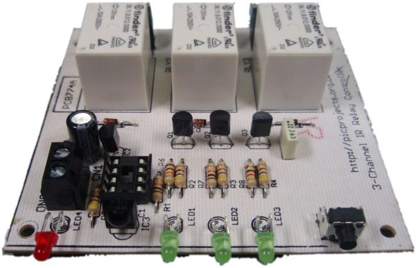
With the controller / driver presented here it is possible to connect multiple drivers to the same serial cable, all attached units then appear to operate synchronously since they’re all receiving the same control data.  The PCB for the RGB PWM Driver has been designed so that it can be used with both the serial control firmware on this page, or the standalone firmware here

Serial Controlled RGB LED PWM Driver

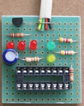
The serial data can be sent from the serial COM port of a PC or using a small dedicated controller that I’ve put together. The Controller code is based on the standalone RGB driver code described elsewhere on this website.  The controller uses the same format for the sequence data as the standalone RGB driver so any SequenceData.inc files you have for the standalone driver can be used with the Serial RGB Controller.

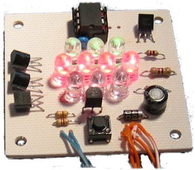
The pictures below show an RGB Driver placed inside a 6″ opal glass light fitting.  I bought this from a DIY store for £4.99 (see here).  When the LED driver is fitted in the base it illuminates the whole globe.  Because most 5mm LEDs have quite a narrow viewing angle you tend to got ‘hot spots’ in the top but overall it’s very effective and makes for great mood lighting.   (In case it isn’t obvious you do not connect the light fitting to the mains electricity supply when used with the RGB Driver!!!)

Also check this mood light by Pete Rus which is based on the Standalone PIC controller
http://www.instructables.com/id/E5A6O59KDPEUSZO1BK/?ALLSTEPS


How it works

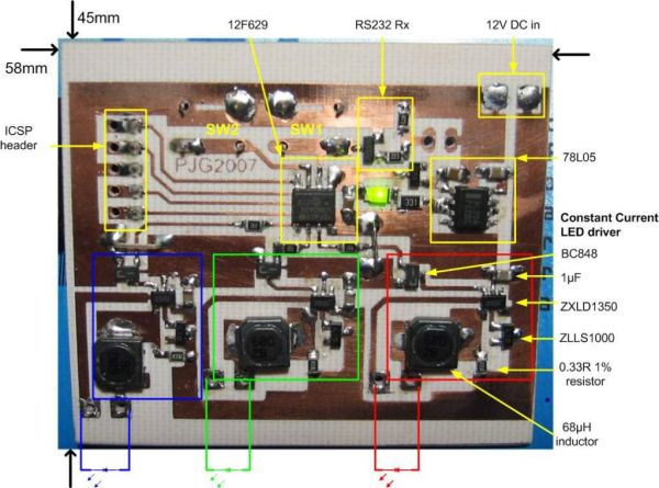
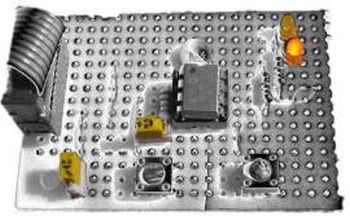
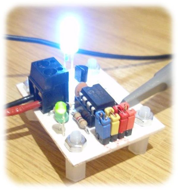
Back to the RGB LED Driver.  Depending on which firmware you program into the PIC this PCB and hardware can operate as either a serial controlled driver or a stand-alone driver (see here). 

Version Firmware
PC Controlled ssrgbdrv.zip
Serial RGB Controller ssrgbdrv.zip
Stand Alone RGB Code rgbsa_inet.zip

Serial Data Format

Serial Data is sent to the RGB PWM Driver using a standard 2400bps asynchronous serial data stream (like you get from the COM port of a PC).  The serial frame format is 1 start bit, 8 data bits, 1 stop bit.   RS232 devices, including the PC COM port, always generate a start bit so when you look at the serial port parameters in Windows you won’t see it as an option.  Use 8N1 for the COM port settings.

 The RGB values for the PWM driver are sent in a five frame packet.

  • The first frame must always contain the value 0x81 (129 decimal)
  • The next three frames contain the 8-bit Red, Green and Blue data for the PWM driver. 
  • The last frame is the checksum.  It should contain the 2’s compliment of the sum of the previous four frames, modulo 256.
    The code snippet below shows the checksum computation in PIC assembler.

movlw     0x81
addfw     RedPWM, W
addfw     GreenPWM, W
addfw     BluePWM, W
sublw     0x00
movwf    
chksum

The Serial RGB Controller will take care of all this for you. However, if you write an application to generate the data from a PC the application itself will need to take care of this.

Controlling from a PC

During development of the Driver I put together a couple of short Perl scripts for testing purposes. The first one takes user entered RGB values and sends them through the PC serial port to the driver.  The second one sends a continuous stream of RGB data to the driver that generates a ‘wave’ effect.  (Both scripts are hard coded to use COM1)

At this point I need to make it clear I am not supporting the Perl scripts.  The ability to send data to the Driver from a PC is a bonus.  If you don’t know Perl or have no previous programming experience you will probably be unable to make use of them.
PLEASE DO NOT e-mail me asking for help with these scripts
I don’t like having to say that, but PIC programming I do for fun; Perl I do not. 

The scripts are written for ActivePerl and require the module Win32::SerialPort. 

Some Perl resources – if you want to learn Perl.

If you write some code for the PC to control the driver boards and you’re prepared to share it, let me know and I’ll be happy to link to it from here.


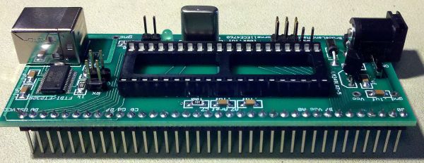
Addressable version of the Serial controlled RGB PWM driver  (added January 2011)

IMPORTANT: Please be absolutely clear about this: it’s available, it’s free, it does work and has been tested but I will not support it, modify it, or help you implement any application with it. Please don’t email me asking for any support – really.

The project on this webpage is a based on code I wrote for an addressable RGB controller, it’s just a cut down version.  At the time I wrote it I didn’t have any supporting software to send data to the addressable modules, for that reason I didn’t make the addressable code available.  I still don’t have any code other than that I used for my own application.  I actually went on to develop the the Serial Addressable RGB PWM LED/Servo Driver which was much better, if a bit more complex.

However over the last four years I’ve been contacted by email on many occasions asking for an addressable version of this project and I’ve let people have the code I’m now making available here on request.

The packet format is described in detail in the PDF file download: Packet format

The source code for the addressable version of the Serial controlled RGB PWM driver can be download from here


For more detail: Serial Controlled RGB LED PWM Driver PIC12F629 based PWM controller for  RGB LEDs

The post Serial Controlled RGB LED PWM Driver PIC12F629 based PWM controller for RGB LEDs appeared first on PIC Microcontroller.


Navigation Lights for Models for PIC12F629

$
0
0

Description

This project was inspired from a post on the Picprojects forum where a member had adapted the RGB Moodlight project for use as a strobe and beacon for a model aircraft.

I thought this would be of interest to others so I’ve put this page together with schematic, examples and free code download.  You can also buy a PIC pre-programmed with the firmware from the Picprojects e-Shop

The sequence data has been custom written to produce the beacon and strobe light effects found on aircraft and boats.

The design has been kept as simple as possible to keep the size small and therefore easy to build into a model.  The circuit has very low power consumption and can be powered from Alkaline or rechargeable batteries.

It is not necessary to use all the outputs, for example the beacon output is also very effective for use in a model Lighthouse.

For those with access to a PIC programmer the source code is available to allow you to customise the sequences and program the PIC with your own effects.

Navigation Lights

Circuit Description

The circuit use a PIC microcontroller, IC1, to drive LEDs with a pulse width modulated (PWM) signal that allows the brightness of each LED to be controlled and faded

There are a number of sequences programmed into the PIC and these can be selected by pressing the sequence select switch SW1.  Each time the switch is pressed the next sequence is selected, when the last sequence has been reached it returns to the first.   The selected sequence is saved to non-volatile EEPROM about 10 seconds after the switch is pressed.  On power-up the last saved sequence is used.

There are two versions of this project and two versions of the firmware which can be downloaded at the bottom of the page.

Basic version: all outputs operate continually while powered on.

Servo Controlled Version:  Outputs are activated under control of an RC servo pulse input.  The outputs still perform the same stobe/beacon/position lights when active but can be turned off under control of the servo signal

The servo pulse is monitored on the GPIO4 input of the PIC.  The signal on the PIC input needs to be active low so the NPN transistor Q1, is used to invert the normal servo pulse signal.

When the servo pulse is between:

  • 1ms – 1.25ms all outputs are off
  • 1.25ms – 1.5ms output GPIO2 is active
  • 1.5ms – 1.75ms outputs GPIO2 and GPIO1 are active
  • 1.75ms – 2ms GPIO2, GPIO1 and GPIO0 are active

Outputs

For the Model Navigation Lights project the function of the outputs is predefined.

  • GPIO0 (pin 7) operates as a anti-collision beacon simulating a rotating light.
  • GPIO1 (pin 6) operates as a strobe
  • GPIO2 (pin 5) is driven with a constant 30% duty cycle signal for navigation lights

LEDs on GPIO2 are driven with a 30% duty cycle which reduces overall battery drain and if you want to dig into the source code and alter the sequence data (in the RCnavLightsData.inc file) you can modify the duty cycle to adjust the brightness.  You could can also leave this output unused and just wire the LEDs directly across the battery (not forgetting the current limit resistors!)

The schematic shows one LED attached to each of the GPIO0 and GPIO1 outputs.  You can if required add a second LED to these outputs by using a second resistor and LED as we have done with the navigation LEDs connected to GPIO2.

The resistor values shown on the schematic for the LEDs are 270 ohms.  This will work for almost all types of 3/5/10mm LEDs.  To increase the LED current and brightness (at the expense of battery life) you can use a lower value resistor but don’t go below 150 ohms.

LEDs

For the navigation lights shown we have used red, green and white LEDs but you can use any colour LED you want to suit your project.   The PIC can directly drive (via a current limit resistor) LEDs up to 25mA per output.  Most small 3/5/10mm LEDs will work.  If you want to drive higher power LEDs you can use the firmware for this project with the Power MOSFET RGB LED Driver project

Capacitor C1 and Resistor R5

Capacitor C1 provides power supply decoupling.  It is important this is fitted as close to the power supply pins of IC1 as possible.  Ceramic capacitors come in either disc or multilayer type – multilayer ones are generally smaller but either type will work.

Resistor R5 is used to pull up the MCLR reset input on the Microcontroller.  If it isn’t fitted the circuit will operate erratically or not at all.

Transistor Q1 and Resistor R6

Only used with the servo controlled version.  Q1 inverts the normal active high servo pulse which is required by the PIC microcontroller.  R6 is a 1K0, 0.25w resistor. 

SW1 Switch

Is used to select the sequence effects.  Any small push-to-make type switch should work here. 

Since the last selected sequence is saved, if you are trying to keep the circuit as small as possible you can make a temporary switch connection to set the sequence you require, them remove it before building it in your model.

SW2 Power Switch

Depending on how you use this project you may be powering it from some other power source that already has a power switch.  If not, you will probably want to fit a SPST (single-pole, single thow) slide or toggle switch to allow the circuit to be switched on and off.

Power Supply

The circuit as shown in the schematic draws an average current of around 7mA operating from a 4.5 volt supply.

It can be powered from three 1.5 volt alkaline batteries or four 1.2 volt NiMH rechargeable batteries.   The PIC microcontroller  will operate with a supply voltage from 3 volts to 5 volts but high brightness LEDs will need a minimum supply voltage of 4 volts to operate effectively.   The power supply must not exceed 5 volts otherwise the PIC microcontroller may be permanently damaged.


For more detail: Navigation Lights for Models for PIC12F629

The post Navigation Lights for Models for PIC12F629 appeared first on PIC Microcontroller.

Wireless controlled lightdimmer using PIC12F629

$
0
0

The meaning from this design is to build it in -i.e. a shaded lamp- and to switch this lamp on and off the normal way, just like it was switched before the dimmer was build in, then you could by exception dimming the lamp more or less with your TV remote control.
When you switch the power on there will follow a soft-start till the lamp burns at the previously adjusted dim level.
With the ‘0’ button in TV mode you can dim the lamp, turn more and less bright.

light dimmer
The remote control should send more then one RC5-signal per button-press seeing that the first one is ignored, this does imply that when the remote button is pressed a short time, there nothing happens.
With the P+ and P- button from a system at choice you can adjust the maximum and minimum dim-levels and with the ‘1’ button the start-up brightness.
The next time when the 230V power is switched on the lamp starts up at the adjusted dim-level.

(Re)adjust the dim-levels:
(only necessary when changing the maximum-, minimum- or start-up- level)
First you should select an unused system on your remote control, i.e. SAT, AMP, VCR2 or DCC mode.

Adjust maximum level: Keep, while switching the power on, the P+ button from the remote control pressed and wait until the lamp burns on desired maximum level.

Adjust minimum level: Keep, while switching the power on, the P- button from the remote control pressed and wait until the lamp burns on desired minimum level. Recommended is to adjust the minimum dim level not to “lamp off” level, because then it’s easy to forget to switch the power off and use unnecessary power.

Adjust start-up level: Keep, while switching the power on, the ‘0’ button from your remote control pressed and wait until the lamp burns on desired level.

Re-adjust the default values (reset): Keep, while switching the power on, the MUTE button from the remote control pressed.

During adjusting the dim-levels, the dim-level changes slower then normal to make adjusting easier.
When letting the button loose and the adjustment is ok, the red- en green LED blinks for a while.
With the -for the dimmer reserved- system selected on the remote control, the P+ (dim-level up) / P- (dim-level down) and button ‘0’ (up/down turn by turn) works too.
Button ‘1’ dims directly to the adjusted start-up level.
Which system on the remote control is choosen doesn’t matter, the ‘0’ button works always in the TV-mode too.

Above described applies to the here downloadable .BAS and .HEX examples, but you can ofcourse modify it to your own wishes.
Keep in mind that a remote control does not always send that what you expected.
The volume from TV, SAT, VCR1 and VCR2 are all the same.
Just as the volumegroup from TAPE, TUNER, CD, etc.
And the ‘0’-‘9’ buttons from system TAPE for example send nothing at all.

See the lists: RC5 system codes and RC5 command codes


For more detail: Wireless controlled lightdimmer using PIC12F629

Current Project / Post can also be found using:

  • pic project ethernet

The post Wireless controlled lightdimmer using PIC12F629 appeared first on PIC Microcontroller.

RGB LED PWM Driver for High Power 350mA LEDs using PIC12F629

$
0
0

Description

This project combines a PIC and three constant current ‘buck’ converters to produce an RGB LED controller that will operate with the the high power 350mA LEDs using PWM to control the LED brightness.  By driving the red, green and blue LEDs with varying pulse widths the controller can generate up to 16 million colours using fades, strobe and static effects.

RGB LED PWM Driver

The use of surface mount components and the low power dissipation in the three current sources allows for a very compact design.

The circuit can drive one or two LEDs in each of the three channels and will work with devices from Luxeon, Prolight, Laminar, Lumileds and others.

The project uses a slightly modified version of the code used for the Standalone RGB controller described elsewhere on this site allowing the sequence data file to be used from the other controllers.

As the board uses surface mount components this project is not really suitable unless you have the soldering skills and experience to work with this technology.

Mood Light

Here we have a mood light made using the circuit described on this page and a light fitting I bought from Homebase DIY store.  It’s a 26cm metal rim flush light fitting with brushed chrome finish.  The frosted glass dome diffuses the light from the LEDs while the silver metal base helps distribute the light evenly.

Assembly was kept very simple.  A hole was drilled in the base for the ‘mode’ switch to fit through and the PCB was fixed down with double sided tape.  Another hole was drilled and then filed square for the DC power connector which was secured with two M2.5 screws.  The RGB LED came from www.led-bulbs.com  It wasn’t fitted to a heatsink so one was made from a piece of copper plumbing pipe cut open and flattened; the heat spreader in the base of the LED was then soldered to the copper.  When the whole assembly is screwed to the metal body of the lamp fitting it provides excellent heat dissipation for the LED.

Once assembled it can be fixed to the ceiling, hung from a wall or simply placed on top of a table or other furniture.  If it’s placed on a flat surface at eye level when you’re sitting down, the low profile of the fitting illuminates upwards without being too obtrusive and the overall effect is very pleasing.

  • The Zetex ZXLD1350 and ZLLS1000 parts are available from Farnell and Digi-Key

  • Inductor Panasonic Part No: ELL6RH680M, Farnell Order Code: 1198602.

  • The inductors listed below appear to be suitable on specification only, I have not tried them. 

    Panasonic
    ELL-6PM680M, Digi-Key part No PCD1714CT-ND

    Sumida
    68µH Digi-Key part No 308-1536-1-ND CR54NP-680KC
    47µH Digi-Key part No 308-1316-1-ND CDPH4D19FNP-470MC
    82µH Digi-Key part No 308-1501-1-ND CDRH6D28NP-820NC
    100µH Digi-Key part No 308-1488-1-ND CDRH6D28NP-101NC


For more detail: RGB LED PWM Driver for High Power 350mA LEDs using PIC12F629

Current Project / Post can also be found using:

  • led ON Off project for pic
  • microcontroller controlling leds
  • Pic18 scrolling led message project

The post RGB LED PWM Driver for High Power 350mA LEDs using PIC12F629 appeared first on PIC Microcontroller.

Intel D945GCLF Small Front Panel using PIC12F629

$
0
0

Description

This is a simple circuit with two buttons and two LEDs to control the D945GCLF Intel motherboard. Both power and reset buttons are included as well as hard disc activity  LED and power status LED. The special feature included is the sleep effect of Apple laptops on the power LED!

Intel D945GCLF Small Front Panel

Design and Implementation

The design goals were:

  • simple to connect to the motherboard;
  • power button;
  • the reset button;
  • possible front usb sockets;
  • Hdd LED;
  • Power LED with sleep effect.

Both power and reset buttons are included in the circuit as well as the LEDs and a pic 12F6xx microcontroller to generate the effect. No USB sockets are included. The connection to the motherboard is also easily done with a flat cable.

Schematic

Schematic Front Panel

The circuit connects directly to the motherboard front panel header with SV1.

Each pin function is enumerated in the user’s manual and also here for convenience.


For more detail: Intel D945GCLF Small Front Panel using PIC12F629

Current Project / Post can also be found using:

  • pic 16f rtos

The post Intel D945GCLF Small Front Panel using PIC12F629 appeared first on PIC Microcontroller.

Test For Presence of Internal Oscillator Calibration Word for PIC12F629

$
0
0

Description

The PIC 12F629 and 12F675 devices have an internal 4Mhz oscillator that enables the devices to be used without an external crystal or RC network.  This frees up one or two pins for I/O use and allows the device to be built into minimum component count designs.

Problems arise if by accident or otherwise, the factory programmed oscillator calibration word, located at program memory address 0x3FF is erased or over written.  If application code tries to read the calibration word and it has been erased, the code will normally crash.

It turns out that erased calibration words on the 12F629/675 PIC are the cause of almost all queries relating to code on my website that uses a 12F629/675.  People using JDM type programmers and associated software seem to have this problem more than most.  This is, in part I suspect, due to the free software / cheap hardware used by the JDM programmer that attracts inexperienced users.

Internal Oscillator

My advise to people with problems is to put the PIC into their programmer hardware and read out the program memory to see if the calibration word is present.  However, experience again shows that many users just become even more confused so I’ve written this application to give a quick Good/Bad test of the calibration word.  There’s also an optional bit of hardware that will display the value of the calibration word if it’s present.


How it works

If the calibration word has been erased, when the application code tries to read it, instead of returning with the calibration value, it wraps back round to the start of program memory as if it had been reset.  When the PIC starts after a Power-on-reset (POR)  certain internal registers are initialised to known values.  If the code wraps back round to the reset vecotr because of a missing calibration word, unlike the Power-on-reset, these registers are not initialised.

The application use the fact that this wrap-around doesn’t affect the internal registers so if we alter the value in a specific register after a power-on-reset we can tell if it has had a Power-on-reset or the code has wrapped back round due to a missing calibration value.

The code indicates the result of the test as Good/Bad by blinking an LED; green LED meaning the calibration word is present, and red LED if it has been erased.

With some extra hardware around a 74HC595 it can also display the value of the calibration word, if present, as a binary number using eight LEDs.  This is optional and the good/bad test works without it being present.

For the basic calibration good / bad test, you only need to build the circuit on the left of the dotted line in the schematic. I deliberately kept it simple so you can quickly and easily build the test circuit.

The circuit around 74HC595 is only used to display the binary value of the calibration word. I added it for a bit of fun, you don’t need it if you just want to test for the presence of the calibration word.

Software

Download HEX code  (for use with either 12F629 or 12F675)

Source code ASM (if you want to see how it works)

For more detail: Test For Presence of Internal Oscillator Calibration Word for PIC12F629

The post Test For Presence of Internal Oscillator Calibration Word for PIC12F629 appeared first on PIC Microcontroller.

LED FX using PIC12F629 Microcontroller

$
0
0

This project produces a number of effects on a set of three LEDs.
You can also produce your own sequence and store it by using the 3 buttons.
You can build the project on Matrix Board or buy a complete kit with pre-programmed chip.
You can also program the chip yourself and use this project as the beginning to: “learning to write your own programs.”

6 Pin 5 Pin Connector

This project takes the place of a number of flashing circuits and can be set so that any of the sequences will show when the circuit is first turned on.
The main purpose of the project is to teach programming, however it also offers a challenge to constructors as it is laid out on matrix board, using surface-mount components. .
We have used SM components for convenience AND for ease-of-use. Once you start using them you will never go back to through-hole components. They are smaller, neater and make a very compact design.
They also make the project look simpler as they “disappear” under the board; or if you are developing a single-sided project, they reduce the size of the final design appreciably.
So, we have two areas of interest. Constructions and programming and it’s up to you to take it on.
The project is designed for all sorts of uses, including models such as train layouts, alarms and similar effects.
It can also be expanded to accept more LEDs and these can be placed on a separate display board.
But the real thing we want to get across, is programming.
This is another example of using a simple 8 pin chip to provide a number of features that would take many logic chips (such as counters and gates) and lots of components to duplicate.
It also highlights our method of hand-coding as an effective way to produce a program.
It is doubtful if the same effects could be produced on any of the pre-packaged microcontroller modules, using a tiny 8 pin chip.
This project uses about 400 instructions to produce the effects and it uses the EEPROM to store the sequence produced by the user (sequence 1) – and show it at turn-on.
In this respect, some of the sub-routines in the program are quite complex and suitable for the advanced programmer. However, if you are a beginner, you can read through the program and most of the sub-routines will be easy to follow as each line of code is explained. You have to start somewhere and this project offers a challenge.
Most projects with a program of this complexity are only available as a pre-programmed chip or only the hex code is available. There is usually no attempt at educating the reader in programming.
That’s the difference between our projects and all others.
We offer a learning curve.
For every hour of effort you put into reading, building and using one of our microcontroller projects, you get the experience of 100 hours of effort that has been put into the design to make it appear simple.
All you have to do is start . . .


For more detail: LED FX using PIC12F629 Microcontroller

Current Project / Post can also be found using:

  • led fx pic16
  • pic led circuit

The post LED FX using PIC12F629 Microcontroller appeared first on PIC Microcontroller.

Small Virtual Wall for iRobot Roomba using PIC12F629

$
0
0

The Virtual Wallis a circuit to mimic the behaviour of the iRobot Virtual Wall/Lighthouse, provided with the robot. It produces the same infrared pattern and the robot sees it as another virtual wall, blocking its path, while vacuuming.

This circuit was built mostly using SMD components to reduce its size, nearly to the size of a 9V battery (PP3/6F22/6LF22/etc).

Small Virtual Wall

Design Considerations

After examining the original virtual wall, with a webcam, I was able to see that it emits infrared light from its top round transparent ring and from a small hole above the switches. The light coming from the top ring prevents the robot from colliding with the virtual wall, if it comes from its sides or from behind. The front hole emits light as a beam. This beam of light is directional and stops at the nearest obstacle, probably a real wall, preventing the robot from crossing it to the other side.

The pattern emitted by the virtual wall is a form of PWM, modulated with a carrier frequency around 38KHz. Below is a picture of the pattern captured using a TSOP1238 and an oscilloscope.

It consists of a sequence of eight bits, encoded as:

So the byte being emitted is 0xA2 or 0b10100010. The pattern repeats itself after a few tenths of milliseconds later.

A circuit to emit a similar pattern will need to output the same 0xA2 pattern, generate the 38KHz carrier frequency and mix the two together. Using a PIC microcontroller it is possible to output the pattern and generate the carrier frequency. Mixing is accomplished by connecting the LED between the PWM output and the carrier output.

A great solution is to use the PIC’s master clock oscillator output to produce the carrier frequency. This is the solution proposed by the circuit below. The PIC clock runs at 160KHz (FOSC) using an RC oscillator and the carrier frequency is available on CLKOUT pin as FOSC/4, at 40KHz.


Schematic

From left to right we see the main switch, the power supply based on a MIC5205-5, 5V/150mA regulator, the microcontroller, two LEDs, one emitting visible light and an infrared one. Connected to the microcontroller’s pin 2 (CLKIN) are R1 and C6 that form the RC pair for the PIC oscillator. There’s also a 5 pin header to connect the programmer (an ICD2 or another compatible one). Click the image to enlarge.

Schematic Small Virtual Wall

The power supply’s MIC5205 is a low dropout voltage, low noise, low quiescent current, regulator very good for battery powered circuits and powerful enough to deliver 150mA. The circuit consumes 3.5mA on average and the IR LED peak current is 25mA mostly because the PIC cannot drive more than 25mA on its pins. The input voltage should be between 5.2V and 16V and I suggest a 9V battery to which you may hold the circuit using velcro or any double sided sticky tape.

As referred above, the PIC’s master clock should be adjusted to FOSC=160KHz using R1. Connecting a frequency counter to pin 3 (CLKOUT) and adjusting R6 until 39KHz or 40KHz are displayed. This adjustment is not critical.


For more detail: Small Virtual Wall for iRobot Roomba using PIC12F629

The post Small Virtual Wall for iRobot Roomba using PIC12F629 appeared first on PIC Microcontroller.


“Mini-Beacon” miniature programmable LED Flasher that is based around a PIC12F629 microcontroller

$
0
0
This project, called “Mini-Beacon”, is a miniature programmable LED Flasher that is based around the PIC microcontroller.  This project grew out of an idea and recommendation posted on RunRyder.com.  The Mini-Beacon basically simulates the light emitted from a rotating light beacon such as those used in older police cars and fire engines.  As seen from the observer’s perspective, as a real rotating beacon revolves, a dim light slowly ramps up brighter and brighter until a flash is seen (light facing directly toward observer), then as it continues rotating, the light slowly dims out and a pause is observed until it repeats over and over again.Mini-Beacon miniature programmable LED Flasher that is based around a PIC12F629 microcontroller  Well, the “Mini-Beacon” simulates this exact effect!  The user can also choose 1 of 12 different flash patterns to be repeatedly displayed.  These patterns include slow, medium and fast rotational beacons (ramp-up & ramp-down speeds), and 3 different selectable flash patterns (single, double and triple flash).  This selection is made by simply shorting a small jumper on the driver board.  This setting is retained in memory so that every time the “Mini-Beacon” is powered up, it will display this pattern.
If this was not enough, the “Mini-Beacon” also allows you to run it in “free-running” mode (connect battery and it repeatedly flashes), or you can control it (on/off) using a spare receiver channel on your R/C receiver (you can use a transmitter stick or switch).   The setting is accomplished using two small jumpers on the board and is described below in detail.  Additionally, and most likely most important… you can also control the Mini-Beacon using a “Mini-Flash” Controller by simply plugging them together!
Design Criteria Summary:
1) Design a simple, cheap but effective “Rotating Beacon” simulator/driver
2) Design so user can easily choose 1 of 12 flash patterns
3) Lightweight and simple to build (DIY)
4) Circuit powers off of existing R/C servo connector
5) Use servo signal to turn on or off the flashing Beacon effect
6) Powers a bright LED (around 600mA max… a one (1) watt Luxeon looks great!)
7) Listen to customers and their needs!   🙂

Parts & Tools List …

1) One (1) PIC 12F629 Chip (preprogrammed with Mini-Beacon code)
2) Two (2) 10K ohm resistors
3) Two (2) 2.2K resistors
4) One (1) Servo Lead/Pigtail wire for Mini-Beacon
5) Four (4) 2 pin header (male) – 3 for Jumpers, 1 for LED/output connector
6) One (1) 2N2222 or PN2222A NPN Transistor
11) One (1) two-row header (mating connector for Mini-Beacon output pins)
12) One (1) piece of heat shrink tubing for assembly
13) Two (2) Shorting Jumpers (one for run mode and the other for programming)

Building Instructions…
Testing and Operation Instructions…

Download the Mini-Beacon User’s Manual below (in PDF format… Adobe reader is required)

The Mini-Beacon controller has a servo cable which can either be plugged into a spare channel on your Radio Control receiver (Rx) or it can simply be connected to a 5-6 volt power source.  Opposite of this servo cable lies a two pin connector (inline with board) that is used to connect your beacon LED.  The onboard output driver/transistor is capable of providing around 600mA to a connected load.  A typical 5mm LED draws 20mA while a 1 watt Luxeon emitter draws an average of 350mA.  3 sets of jumpers/pins located on the Mini-Beacon are used to either set the flash pattern (1 of 12), set the servo control function, or allow the controller to free-run.  First thing you will obviously need to do is connect an LED to the Beacon output pins (see picture above, observe polarity).  Be sure to use the proper series current limiting resistor inline (series) with one of the LED leads (typically 56-120 ohms).Mini-Beacon miniature programmable LED Flasher that is based around a PIC12F629 microcontroller schematich
There are two ways you can operate the Mini-Beacon controller.  You can either set it up so it’s in “free-running” mode (apply power, and it flashes continuously until power is removed), or you can connect it up to a spare R/C receiver servo channel and control (on/off) the flashing pattern of the beacon using a stick, slider or switch on your transmitter (aka Servo Control Mode).  The Mini-Beacon has two jumpers that allow you to set these two functions (labeled “Servo Jumper” and “Free-Run” on the picture above.  Only one of these jumpers should be connected at one time.


The post “Mini-Beacon” miniature programmable LED Flasher that is based around a PIC12F629 microcontroller appeared first on PIC Microcontroller.

LED Strobe for PIC12F629 / 675

$
0
0

 Description

This project functions as a simple strobe for driving an LED.  The use of an output transistor allows it to pulse the strobe LED with a current up to 100mA.

Four jumpers provide options for changing the pulse width, strobe repeat interval and single or double strobe flash.  The programmer ready code has default timings which are easily customised by editing values in the PIC’s EEPROM at programming time.

This is one of those applications where it’s arguably better than a 555 timer based solution but in practice you could build it with a 555 timer faster than you can write the PIC code.  However it only needs the code writing once, I’ve done that and designed a small PCB too so away you go.LED Strobe for PIC12F629 675

Schematic

Circuit Description

The circuit provides a LED strobe function with jumper selectable operating modes.

The strobe interval can be configured using 4 jumpers for 1,2,3 or 4 seconds; strobe on time of 30mS or 100mS and single or double strobe pulse.

Since the PIC can only supply 25mA from its I/O pin a transistor is used to increase the maximum current driven through the LED.  This transistor has a maximum collector current of 100mA which is adequate for driving most types of 5mm LEDs.  The PIC could be used to control a higher powered output switch if desired.

The value of R3 series current limiting resistor for the strobe LED has been selected on the conservative side rather than providing maximum brightness.  With a 5 volt supply and LED with 1.8V forward voltage yields current of approximately 47mA.

The strobe LED can either be installed on the PCB in position LED1 or off-board via connector CN2.  If the off-board option is used do not install a LED into position LED1 on the PCB.

LED2 is a monitor LED, if the off-board strobe LED is used, this LED can be useful for monitoring the operation of the circuit.  If you don’t want this option, just omit LED2 and R4.

Capacitor C1 is used to decouple the 5 volt power supply rail.  If you are building the circuit on a breadboard or stripboard you should ensure it is located close to the PICs Vdd connection (pin 1).

The input voltage must not exceed 5 volts.  It can run from as low as 3 volts but you will need to modify the Strobe LED resistor value.  Also be aware of the LED forward voltage; some high brightness LEDs and in particular white LEDs and some blue and green LEDs have forward voltages in excess of 3 volts.

The operating modes are selected by using jumper block JP1.  If you are building the strobe for a specific application you may want to hardwire inputs to ground as required rather than fit the jumper pin header.

Choosing R3 / LED1

Obviously we want the strobe LED to be as bright as possible.  It is important that the series resistor R3 is chosen so that the LED current does not exceed the manufacturers rating.  Since different LEDs have different maximum forward current and voltage ratings you must select this resistor to suit the specific LED you are using.

For other LEDs you can use this site to calculate the resistor needed http://led.linear1.org/1led.wiz  When you go to this site it asks for the source voltage.  This will be 5 volts, or if you’ve used batteries to power the strobe, the total battery voltage.  Also note that driver transistor Q1 is only rated to 100mA so do not exceed this even if the LEDs used can.

Strobe Operating Modes

The section refers to the default timings used in the programmer ready firmware download.

The pulse width, interval and strobe mode are user selectable using the JP1 jumper block.  There are two strobe modes, single and double pulse.  The double mode has a (default) 175mS off-time between the two pulses.  As shown in the diagram below, the interval is measured from the end of one pulse group to the start of the next group.

 Jumper Settings

Customising the strobe timing
The timers for the pulse width, interval and double mode gap are all configurable by editing the values in the PICs EEPROM before writing the HEX into the PIC.  This is nice and easy to do and doesn’t require reassembling the code or anything complicated.  Just load the HEX file from the firmware download section into your programmer application.  Edit the values in the EEPROM as shown below and then write the code and EEPROM data into the PIC.LED Strobe for PIC12F629 675 schematic

Suppose you want a pulse width of 40mS (40 x 1mS) and an interval of 1.3 Seconds (13 x 100mS) you would set the data in address 00 to 28 (40 decimal == 28 hexadecimal).  For the 1.3 second interval change the data in address 03 to 0D (13 decimal == 0D hexadecimal).

Values shown in the example above are the default values in the firmware download.  If you don’t modify them it will uses these timings.

Converting decimal values to hexadecimal

Depending on your programmer the values you need to enter will probably be in hexadecimal, easiest way to convert decimal values to hexadecimal is Google, see example below.  The prefix 0x in the result simply tells us the value is in hexadecimal (hex for short).


For more detail: LED Strobe for PIC12F629 / 675

The post LED Strobe for PIC12F629 / 675 appeared first on PIC Microcontroller.

RGB LED PWM Driver for High Power 350mA LEDs V3 using PIC12F629

$
0
0

Description

As featured in Electronics Weekly Gadget Freak (20/02/2008)

The main reason I made this version is that I wanted to fit it in to the base of an Ikea Mylonit lamp. This lamp is made entirely from glass and has a small recess in the base with an entry for the power lead.  Since it had nowhere to fit a separate power connector but did have a slot for a power lead to pass in to the base, I needed to make a PCB with a DC power connector in the centre of the board.  At the same time I took the opportunity to tweak the circuit slightly and left out things it didn’t need. The changes are detailed below.  Please note that the original version on the main page is still perfectly okay and you may find the single sided PCB easier to make.

RGB LED PWM Driver

Changes for R3

  • This version uses a double sided PCB. Dimensions are approximately the same as the original version.

  • Removed the second push button switch and components for the RS232 serial interface.

  • Added 22K resistor between MCLR input and Vdd.  This eliminates the need for a jumper on the ICSP header in normal operation. (If you use a 12F683 you can omit this resistor as well since it has an internal pull-up)

  • Provision for a surface mount DC power socket.

  • Removed the power-on LED and series resistor.

  • Added 47K pull-up resistors to the transistor drive circuit.  On the original version, when it first powered on the RGB LEDs would flash at 100% brightness very briefly.  This is caused by the PIC I/O lines defaulting to inputs at power-up and until the software starts and sets them as outputs the PWM inputs to the ZXLD1350 are enabled.  This modification prevents this from happening. NOTE: it’s purely for aesthetics, not a fix for a design fault.

  • In all other respects the circuit and software is identical to the version 2 design on the main page.


Schematic

Version 3 PCB

Construction Notes

You must drill vias and solder links between the ground plane and the top side of the board. These are circled in Yellow.There are also six vias linking tracks on the top and bottom of the PCB. These are circled in GreenYou must ensure you add these or the circuit will not function correctly, if at all.  

The pad size for the three inductors is SM2512.  There are such a variety of inductors that could be used here with so many different footprints.  I’ve left some clear area around the pads to facilitate the use of various inductors but you should make sure that the ones you do use aren’t going to touch other areas of copper.  This may require some creative positioning of the inductors.


For more detail: RGB LED PWM Driver for High Power 350mA LEDs V3 using PIC12F629

Current Project / Post can also be found using:

  • proteus project on led blink fade
  • led pic pro
  • mosfet pwm
  • pic chip led projects

The post RGB LED PWM Driver for High Power 350mA LEDs V3 using PIC12F629 appeared first on PIC Microcontroller.

A modified version of the “Air diplay” adapted to be used in a bicycle using PIC12F629 microcontroller

$
0
0

Anthony from Cumaná, Venezuela, made his own “Persistence of vision” (POV) display, similar to my Air Display but it can be mounted on any bicycle wheels and it displays fifteen messages in Spanish.

Air diplay adapted schematic

Here is the PCB with each part of the project. It uses a 12F629, works with a voltage of 3Volts

This is the PCB top view to determine the location of each part. The yelow ones are the resistors, the red ones are the LEDs (works better with RED leds) and there is a jumper under the microcontroller PIC 12F629.

Air diplay adapted schematic 2

Your can DOWNLOAD THE HEX FILE here. Right click the link and choose “SAVE AS…”

For more detail: A modified version of the “Air diplay” adapted to be used in a bicycle using PIC12F629 microcontroller


The post A modified version of the “Air diplay” adapted to be used in a bicycle using PIC12F629 microcontroller appeared first on PIC Microcontroller.

Schaer+ Programmer using PIC12F629 microcontroller

$
0
0

Description

Schaer is a generic programmer circuit capable of uploading and downloading firmware to/from several electronic devices like microcontrollers and eeproms. This and other programmers came to my attention when I was working in CAMBADA, the robotic soccer team from the University of Aveiro, and since all other programmers available there were too expensive for me to buy or build, I decided to build one that was simple and cheap!

schaer whiteboard

This programmer has given me lots of trouble with high capacity PICs and I decided to abandon the project and build a ICD2 clone for MPLAB. What rests here are just the remains of the project.

Design and Implementation

I can’t remember where I found the first schematic on the web but after testing it in a white board I decided it was best to try a definitive solution on a PCB. The circuit is very straightforward: it gets its control signals from the parallel port and sends it to the PIC being programmed. It needs one power supply of at least 15V and generates its 13V and 5V with 78XX regulators.

Schematic

Schematic schaer

The schematic is a copy of the original schematic found on the web. At the top of this page is the first implementation on a prototype white board.


For more detail: Schaer+ Programmer using PIC12F629 microcontroller

The post Schaer+ Programmer using PIC12F629 microcontroller appeared first on PIC Microcontroller.

3-Channel IR Relay Controller with user programmable IR commands for PIC12F629

$
0
0

Description

This project is a 3 channel infrared (IR) remote controlled relay driver.  It works with 12-bit SIRC IR signals as used by Sony remote controls.

The controller also features the ability for the user to ‘program’ the commands it will respond to using  the IR remote control.   Each of the three relay channels can also be individually configured for either toggle or momentary switch action.

Although this project has been designed around the control of three relays, the PIC microcontroller can be incorporated in to any application where up to three logic level outputs are required to be remotely controlled.

Relay Controller

The controller uses Microchip’s low cost PIC12F629 microcontroller along with a handful of

easy to find  components making it cheap and easy to construct.  Everything you need to know to build this project, including the firmware code is right here on the project page.  If you don’t have access to a PIC programmer you can buy the PIC chip pre-programmed from the online-store

Don’t forget to check out the accompanying mini IR remote control which can be used with this project.

Download schematic in PDF

Circuit Description

The board is powered from a 12 volt DC supply input.  This is fed through diode D5 which provides protection from a reversed connection of the power supply. Capacitor C2/C3 filter / decouple the 12 volt supply.  The 12 volt input is fed to a 78L05 voltage regulator to provide the 5 volt supply required for the PIC microcontroller IC1 and the IR receiver IC3.

The IR signal is detected and demodulated by IC3 a TSOP4838 IR receiver IC.  This part was chosen because it has a low supply current requirement – typically around 1.5mA.  The output from the detector is fed to the GP2 input of microcontroller IC1.  When a signal is received by the TSOP4838 it  pulls the GP2 input on the PIC low, when no signal is received it is pulled high by an internal pull-up resistor.   The firmware programmed into the PIC12F629, IC1 decodes the signal using the 12-bit SIRC protocol (see download section).  

n.b. The circuit and code will work without modification using either a PIC12F629 or PIC12F675

The relays are switched on by microcontroller IC1 via driver transistors Q1, Q2 and Q3.  These are low power NPN transistors, in this case BC547 but virtually any small NPN transistor will work here as they only need to switch around 30mA – BC548 or BC549 would also work well.  The relay status LEDs are connected in series with the base of the relay drive transistor. When one of the outputs of IC1 goes high, around 5mA passes through the respective LED and 470ohm resistor to the base of the transistor, causing both the LED and transistor to turn on and activate the relay.  When the output of IC1 goes low, the 10K resistor holds the base of the transistor at 0V ensuring it turns off and the relay deactivates.  The diodes across the relay coils protect the transistor from the back EMF generated by the relay coil when it is de-energised.

LED 4 is a status LED, in normal operation it indicates when an IR command is being received by flashing at 20Hz.  It is also used to indicate that the controller is in setup mode.  Switch S1 is used to enter and exit setup mode, details of this are covered in the User Programming section.

For more information on the SIRC infrared protocol and codes see:

Download PCB artwork in PDF
Download PCB overlay in PDF

PCB dimensions are 80mm x 75mm approx.

Suggested hole drill sizes:

  • terminal blocks and S1 metal frame drill at 1.1mm
  • relays drill at 1.5mm
  • U1, U3 drill at 0.85mm
  • PCB mounting holes drill at 3mm
  • everything else drill at 0.75mm

Component List

You can buy all the parts needed to build this project from most component suppliers world wide. In the UK you can get everything from Rapid Online and I’ve included a parts list with their part numbers below.


For more detail: 3-Channel IR Relay Controller with user programmable IR commands for PIC12F629

Current Project / Post can also be found using:

  • pic microcontroller ethernet project
  • interfacing circuit for ethernet and pic18
  • microcontroller lan communication
  • microcontroller led light

The post 3-Channel IR Relay Controller with user programmable IR commands for PIC12F629 appeared first on PIC Microcontroller.

PIC PROGRAMMER MkV using PIC12F629

$
0
0

PIC Programmer MkV is designed to get you into PIC Programming for just a few dollars. It uses just 12 components. Most of them will be in your “junk-box” and the PC board is a small piece of matrix board. It’s the cheapest way to get started.
As well as PIC PROGRAMMER MkV you will need these 4 things:
1. A desk-top computer with DB-9 serial port. (This programmer will not work on a lap-top computer and may not work with Vista.)
2. A software program called IC-Prog 105C-a and some helpful notes to guide you with setting up your computer. (This project is not suitable for In-Circuit Programming. You need to remove the chip from the project you are creating and program it in the 18 pin socket on the programmer. Eight pin chips are fitted with pin 1 aligning with pin 1 of the socket.)
3. A PIC chip, either PIC12F629 or PIC16F628 and
4. A project using one of these micros.

PIC Programmer MkV

This will get you into producing a MICROCONTROLLER PROJECT.
We have concentrated on two PIC chips. An 8 pin and 18 pin chip. The 8 pin chip can be either PIC12F629 or PIC12F675 and the 18 pin chip is PIC16F628 or PIC16F675.
The programmer will work with many other chips but we are concentrating on these two types to get you started.
Not only is a microcontroller project simpler than using lots of discrete chips, but it can be cheaper and easier to modify and provide a greater range of features than lots of individual chips.
On top of this you can produce a project that requires a program and this can be “locked” from prying eyes. This makes it saleable and you can protect your Intellectual Property – and make money.
Talking Electronics has produced a range of simple projects and provides assistance to get you into programming and creating projects that you have only “dreamed of.”
Getting into microcontroller programming will change your life.
But before we go any further, let’s build the programmer:

BUILDING THE PIC PROGRAMMER
The circuit is constructed on a small piece of matrix board. All the components are readily available and the 3 red LEDs act as a visual indication that the programmer is operating as well as creating a 5v rail for the chip. The other two LEDs indicate the clock line is operating and 13v is present on the programming pin. It does not indicate the actual voltage – you will need to measure the voltage with a voltmeter to determine this.
A 470R resistor is connected between pins 4 and 8 inside the plug. This allows 4 lines to be taken to the project.

WIRING THE PLUG AND LEAD
The lead can be any 4-core cable. We have used 4-core telephone cable. Follow the diagram to prevent any mistakes. The 470R resistor is soldered to pins 4 and 8 of the female plug.

For more detail: PIC PROGRAMMER MkV using PIC12F629

The post PIC PROGRAMMER MkV using PIC12F629 appeared first on PIC Microcontroller.


Capacitance Meter MkII using PIC12F629

$
0
0

This project is specially designed to measure surface mount capacitors in the range 1p to 920n and electrolytics in the range 1u to 100u.
The biggest problem with surface mount capacitors .  .  .  they are not identified!
And you cannot determine their value by the size of the component.
This makes it very difficult.
Unless you know the value when taking it off a reel, they can get mixed up and fitting a 22n in place of a 47p will create a lot of problems.

This project is a low-cost piece of test equipment especially designed to test these devices in the range 1p to about 100u .  .  . capacitors 1u and larger are identified on their body with values such as 105 for 1un, 106 for 10u and 107 for 100u.
Surface-mount capacitors are also fiddly to hold and test at the same time, so we have designed a set of tapered contacts where the capacitor is held with tweezers and moved down the contacts until it is gripped by the contacts. Then a reading can be made.
Simply hold the button ON and the display will produce a reading.

Capacitance Meter MkII

The CIRCUIT
The circuit diagram is very simple but a lot of “design consideration” has gone into the 4 components used to detect the value of a capacitor. The biggest problem is the range of capacitance we want to measure. The circuit detects capacitance values from 1p to 100u. This is a range of 100,000,000:1 or 108:1

The normal way to measure the value of a capacitor is to charge it via a resistor and see how long it takes to charge to 66% of the charging voltage. This length of time is called a TIME CONSTANT and applies to a capacitor when a particular “charging resistor” is used.
For instance, if we have a 1p capacitor and 100k resistor, the time constant will be:
(100,000 ohms x 1Farad) / 1,000,000,000,000 = 0.1microseconds.
This means a 1p capacitor will charge in 0.1 microseconds when a 100k resistor is used to charge it.
We are using a PIC12F629 microcontroller and each instruction-cycle takes 1 microsecond. This means we can only “look at” the charge on the capacitor every microsecond and by this time it will be already charged  – as it only takes 0.1 of a microsecond.
In fact the fastest-rate we can look at the charging of a capacitor is every 3-5 microseconds due to 3 instructions needed to create a “look” loop and this means the smallest capacitance we can detect is 50p and increments in amounts of 50p.
However there is one other feature built into the PIC micro that operates at up to 10MHz. It is called the COMPARATOR MODULE, but to make it easier to understand how it works, we will call it an OP AMP.
An Op-Amp has a NON-Inverting input (+) and an Inverting Input(-) and an output.
We have already discussed the OP-AMP in another article on Talking Electronics website, however the essential points to note are these.
The “+” input of the op amp can be supplied from an internal reference voltage and we have selected this voltage to be 60% (3v) of the supply voltage.
Since this voltage is a reference voltage, it must be fixed and that is why we have used a voltage regulator to supply an accurate 5v for the supply-rail.
When 3v is supplied to the “+” input of the op amp, the output is HIGH when the “-” input is at any voltage below 3v.
As soon as the “-” input rises a few millivolts above 3v, the output instantly goes LOW.
When the “-” input goes a few millivolts below 3v, the output goes HIGH again.
This means the “-‘ input only has to change a few millivolts and the output changes from HIGH to LOW.
The “-” may only need to be 1mV above and 1mV below 3v for the output to change. We don’t know the exact value but it does not matter. We just need to remember this characteristic.
Now we need to create a circuit that will charge a capacitor via a resistor, then discharge the capacitor to create an oscillator. By measuring the frequency of the oscillator we can determine the  value of the capacitor.
If we place a capacitor on the inverting input with a resistor to the output of the op amp, we will create an oscillator. But the capacitor will only have to charge and discharge a few millivolts for the circuit to oscillate and this will produce a very high frequency oscillator. We cannot deal with a high frequency oscillator so we must improve the circuit.
By adding a diode across the charging resistor we will almost fully discharge the capacitor each time the output goes low and this will increase the charging time.
We have also added a 1k resistor so the charge on a large capacitor does not damage the output of the op amp when it goes low and this will also gives us a known amount of discharge.


For more detail: Capacitance Meter MkII using PIC12F629

The post Capacitance Meter MkII using PIC12F629 appeared first on PIC Microcontroller.

Whistle Key Finder using PIC12F629

$
0
0

This project uses one of the smallest chips in the PIC microcontroller range, the PIC12F629 and you can learn to program it and experience the thrill of making something yourself and see what goes into writing a program.
Even a program as simple as this one is not easy to put together and if you are starting from scratch, you will need a programmer (a “burner”) and all the data that goes with “burning” and creating a program for the micro. We use the PICkit-2 as it is the cheapest and best. It comes with USB cable and 2 CD’s containing the programs needed to “burn” the chip. You will also need NotePad2 to write your .asm program
(use Whistle.asm or Whistle.txt as a template for your program).

Whistle Key Finder

The PC board includes 5 pins for “In Circuit Programming” via PICkit-2 and you will be encouraged to use surface-mount components to interface the piezo diaphragm to the chip.
One of the clever parts of the circuit is the piezo is used to detect the sound and then produce the beep-beep-beep reply.
Be reminded that not all piezo diaphragms are the same. Some are very sensitive when detecting audio and others are not sensitive at all.
Ours produces an output of about 20mV to 50mV when whistling up-close, while an insensitive diaphragm will produce only a few millivolts.

The CIRCUIT
The circuit consists of two common-emitter stages with enough gain to produce a rail-to-rail signal when the piezo detects a whistle.
We are not concerned about distortion or over-driving the chip as we want a fairly square wave.
A super-alpha arrangement was tried using two transistors but it did not work at all.
It is surprising how “theory” does not always work in practice and that’s why you must try everything before settling on a result. Each stage has a gain of approx 70, making the total approx 5,000. This allows a 1mV signal from the piezo to produce a rail-to-rail waveform.
As we mentioned, the interesting feature of the circuit is the use of the piezo to detect a signal and then produce a beep. This has been done by making the piezo “float.”
It is not connected to any rail and although it is connected to pins of the chip, these can be made “inputs” and thus become high impedance.
The 4k7 on the base of the transistor allows the piezo to be driven by the chip in “bridge-mode” where the pins are alternately made high then low so that twice the supply voltage is effectively delivered across the piezo to increase its output.
Without the 4k7, the lead of the piezo would not rise above 0.6v due to the base-emitter voltage limitation.
When the piezo is required to detect a signal, one lead is connected to 0v via a pin of the chip and the other lead connects to the base via the 4k7. The pin on the chip is changed to “input” during this operation.
When the piezo is activated, the signal is also amplified through the transistors but the chip is not in detection-mode and this signal is not detected.

SURFACE-MOUNT COMPONENTS
To keep in line with miniaturisation, we have used surface-mount components. Once you start using surface-mount components, you get hooked. Through-hole components seem enormous. You will need fine tweezers to hold them in place while one end is soldered.
Always use very fine solder as you only need very little for each component and the main reason for adding extra is to take advantage of the flux to clean the connection. Always solder resistors with the value showing. Capacitors don’t have values marked on them and you cannot work out the value by the size of the component.
That’s why you have to know the value before taking them out of their “carrier.”

CONSTRUCTION
You can build the circuit on any type of PC board and we have used a small prototype board that needs some of the tracks cut to suit the placement of the 8 pin IC socket.
The kit of components comes with all the parts you need to get the project working, including a pre-programmed chip and a prototype PC board that needs some tracks cut.
We will not describe any construction details as most constructors will be adept in placing components. The only thing to remember is to cut the tracks before fitting the IC socket as some tracks run under the socket.

To modify the program you will need a PICkit-2 programmer and this comes with 2 CD’s containing all the software needed for In-Circuit Programming.
You will also need a lead to connect the programmer to your lap top via the USB port (comes with PICkit-2) and an adapter we call a 6pin to 5 pin Adapter to connect the PICkit-2 to your project. (The photo below shows the prototype 6pin to 5 pin Adapter. A PC board is now available for the adapter.)


For more detail: Whistle Key Finder using PIC12F629

Current Project / Post can also be found using:

  • gas detector using pic microcontroller

The post Whistle Key Finder using PIC12F629 appeared first on PIC Microcontroller.

Long Period Astable Timer using PIC12F629

$
0
0

Description

This software functions as a long period astable mutivibrator.  The mark and space period can be set from 1 second up to a maximum 65535 seconds (18h12m15s). Using the internal 4Mhz RC oscillator delays with an accuracy of 99% or better can be achieved 

The code also implements an edge triggered reset and an active low hold function.  The reset edge can be configured for rising or falling edge.  The hold function is active low and stretches the timed period for as long as the hold input is held low.

Long Period Astable Timer

In addition to this up to 450 mark/space time pairs can be used which are executed sequentially allowing complex pulse trains to be generated.

By connecting the hold input to the Q output, the code can also be made to function as an edge-triggered monostable timer, using the reset input as the trigger.

The code will run on a PIC 12F629 or 12F675.

At power on and after an edge triggered reset the outputs enter a mark state with the Q output going high and the notQ output going low.  The first time entry is then read and the code waits for the number of seconds specified.  When this period has elapsed a Space state is entered with the Q output going low, notQ output high and the next time entry is read. 

When the Hold input is taken low the output remains unchanged and the timer is stopped, effectively stretching the current time period. When the Hold input returns high, the timer continues.

If the Reset input is triggered while Hold is low, the outputs are reset to Q == high, notQ == low and the timer is loaded with the first entry from the LongDelayTimes.inc file. It them remains in the Hold state until the Hold input returns high.

Accuracy of timings

Since the timings are generated from the PICs internal 4Mhz RC oscillator the accuracy is subject to the tolerances specified in the Datasheet with respect to operating voltage and temperature. The software itself will generate an accurate timing but any deviation in the RC oscillator from 4Mhz will result in the time period deviating.  You should therefore test the accuracy before committing it to an application.

Since the PIC calibration word can only be correct at a specific supply voltage and temperature it is advisable to calibrate it at the supply voltage it will operate at in the final application.  This will help considerably in obtaining accurate timings.

My investigations with a number of PICs from different batches suggest that Microchip calibrate the PIC at a supply voltage of 3.5 volts.  Therefore if you’re operating it from a 5 volt supply it will be running slightly too fast.  

In the trace below the factory calibration value was 0x2C, the value when recalibrated with a 5 volt supply was  0x34.  For a programmed delay of 60 / 300 seconds it is showing 59.85/ 299.3 seconds which is 99.7% accurate.  This would result in an error of 3m16s over 18h12m.

For more detail: Long Period Astable Timer using PIC12F629

The post Long Period Astable Timer using PIC12F629 appeared first on PIC Microcontroller.

PIC RGB Power Board using PIC12F629 microcontroller

$
0
0

Description

Power Pic RGB is a circuit that generates random RGB colors using a powerful 3W RGB LED and fades

between them.

The initial project goal was to develop the fading algorithm which was successfully achieved. This time the idea was to drive a Prolight 3 Watt RGB LED and place it inside a nice white globe! On the right is a picture of the first prototype board eith a small board attached that doesn’t belong to this project.

PIC RGB Power Board

Design and Implementation

The circuit is basically the same with the addition of 3 BS170 mosfet transistors to drive the LED and a powerful 5V regulator. The PIC is the same but the code has a small big difference, explained below!

Schematic

From left to right we can see the power supply based on a 7805 5V 1A regulator, the microcontroller and finally on the right the three mosfets that will drive the LED. Click the image to enlarge.

Schematic PIC RGB Power Board

Each mosfet can drive a maximum 600mA through its drain but according to Prolight each LED (red, green and blue) can only sustain 300mA which makes this mosfet perfect for the job.

Summing the 3 LED currents we get 900mA not counting the current consumed by the PIC and the 7805 itself which should be around 3 or 4 mA. The 7805 is able to supply 1A of current with a proper Heatsink.


For more detail: PIC RGB Power Board using PIC12F629 microcontroller

Current Project / Post can also be found using:

  • measurement of battery charger using 8051 microcontroller

The post PIC RGB Power Board using PIC12F629 microcontroller appeared first on PIC Microcontroller.

LED Strobe for PIC12F629

$
0
0

Description

This project functions as a simple strobe for driving an LED.  The use of an output transistor allows it to pulse the strobe LED with a current up to 100mA.

Four jumpers provide options for changing the pulse width, strobe repeat interval and single or double strobe flash.  The programmer ready code has default timings which are easily customised by editing values in the PIC’s EEPROM at programming time.

This is one of those applications where it’s arguably better than a 555 timer based solution but in practice you could build it with a 555 timer faster than you can write the PIC code.  However it only needs the code writing once, I’ve done that and designed a small PCB too so away you go.

Download schematic in PDF

Circuit Description

The circuit provides a LED strobe function with jumper selectable operating modes.

LED Strobe

The strobe interval can be configured using 4 jumpers for 1,2,3 or 4 seconds; strobe on time of 30mS or 100mS and single or double strobe pulse. 

Since the PIC can only supply 25mA from its I/O pin a transistor is used to increase the maximum current driven through the LED.  This transistor has a maximum collector current of 100mA which is adequate for driving most types of 5mm LEDs.  The PIC could be used to control a higher powered output switch if desired.

The value of R3 series current limiting resistor for the strobe LED has been selected on the conservative side rather than providing maximum brightness.  With a 5 volt supply and LED with 1.8V forward voltage yields current of approximately 47mA.

The strobe LED can either be installed on the PCB in position LED1 or off-board via connector CN2.  If the off-board option is used do not install a LED into position LED1 on the PCB.

LED2 is a monitor LED, if the off-board strobe LED is used, this LED can be useful for monitoring the operation of the circuit.  If you don’t want this option, just omit LED2 and R4.

Capacitor C1 is used to decouple the 5 volt power supply rail.  If you are building the circuit on a breadboard or stripboard you should ensure it is located close to the PICs Vdd connection (pin 1).

The input voltage must not exceed 5 volts.  It can run from as low as 3 volts but you will need to modify the Strobe LED resistor value.  Also be aware of the LED forward voltage; some high brightness LEDs and in particular white LEDs and some blue and green LEDs have forward voltages in excess of 3 volts.

The operating modes are selected by using jumper block JP1.  If you are building the strobe for a specific application you may want to hardwire inputs to ground as required rather than fit the jumper pin header. 

Choosing R3 / LED1

Obviously we want the strobe LED to be as bright as possible.  It is important that the series resistor R3 is chosen so that the LED current does not exceed the manufacturers rating.  Since different LEDs have different maximum forward current and voltage ratings you must select this resistor to suit the specific LED you are using.

For other LEDs you can use this site to calculate the resistor needed http://led.linear1.org/1led.wiz  When you go to this site it asks for the source voltage.  This will be 5 volts, or if you’ve used batteries to power the strobe, the total battery voltage.  Also note that driver transistor Q1 is only rated to 100mA so do not exceed this even if the LEDs used can.

Strobe Operating Modes

The section refers to the default timings used in the programmer ready firmware download.

The pulse width, interval and strobe mode are user selectable using the JP1 jumper block.  There are two strobe modes, single and double pulse.  The double mode has a (default) 175mS off-time between the two pulses.  As shown in the diagram below, the interval is measured from the end of one pulse group to the start of the next group. 


For more detail: LED Strobe for PIC12F629

The post LED Strobe for PIC12F629 appeared first on PIC Microcontroller.

Viewing all 85 articles
Browse latest View live


<script src="https://jsc.adskeeper.com/r/s/rssing.com.1596347.js" async> </script>