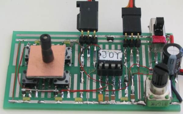
Quantcast
Viewing all 85 articles
Browse latest View live

Tiny Remote for iRobot Roomba using PIC12F629

Description

The Tiny Remoteis a very compact infrared remote control with only two buttons to control an iRobot Roomba. It produces three different infrared control signals that the robot interprets as Clean, Spot and Virtual Wall/Lighthouse.

Image may be NSFW.
Clik here to view.
Tiny Remote for iRobot Roomba

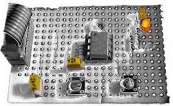
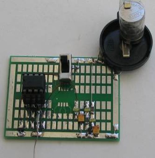
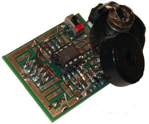
The circuit is built mostly using SMD components to reduce its size, nearly to the size of a keychain and is powered by a CR2032 coin battery.


Design Considerations

After having designed the virtual wall, I wanted to be able to remotely control the robot. Most of the work had already been done on the assembler software of Virtual Wallso I was left with the tasks of redesigning the power supply and add two buttons.

Power supply considerations:

  • It should be powered by a CR2032, CR2025 coin battery or similar;
  • Idle current consumption should be 0 (zero) because these batteries have small capacities;
  • Ideally the circuit should only consume power from the battery when a button is pressed;
  • A voltage step-up is needed because 3V are not enough to power the PIC and infrared LED.


Like the  Virtual Wall, the infrared pattern generator:

The infrared patterns emitted by the remote control are a form of PWM, modulated with a carrier frequency around 38KHz~40KHz. Below is a picture of the lighthouse pattern captured using a TSOP1238 and an oscilloscope.

Transmitting commands on the remote:

  • Button 1 sends the Spot command;
  • Button 2 sends the Clean command;
  • Both buttons simultaneously send the Virtual Wall/Lighthouse command;
  • Keeping buttons down will repeat its command until they are released.

No Stop command is included in the remote because it’s not needed! Each command, Clean or Spot, act as start when the robot is stopped and stop when it’s already running.


Generating the infrared 38KHz~40KHz carrier frequency:

Using a PIC microcontroller it is possible to output the infrared pattern and generate the carrier frequency. Mixing is accomplished by connecting the LED between the PWM output and the carrier output.

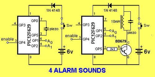
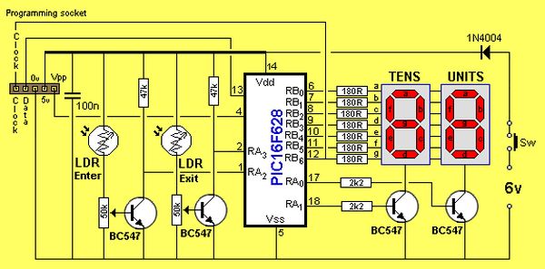
A solution is to use the PIC’s master clock oscillator output to produce the carrier frequency. This is the solution proposed by the circuit below. The PIC clock runs at 160KHz (FOSC) using an RC oscillator and the carrier frequency is available on CLKOUT pin as FOSC/4, at 40KHz.


Schematic

Image may be NSFW.
Clik here to view.
Schematic Tiny Remote

From left to right we have the CR2032 3V coin battery, the power supply based on a MAX619 regulator, the microcontroller 12F629, two LEDs, one emitting visible light and an infrared one and two push buttons. Connected to the microcontroller’s pin 2 (CLKIN) are R1 and C6 that form the RC pair for the PIC oscillator. There’s also a 5 pin header to connect the programmer (an ICD2 or another compatible one). The two diodes D1 and D2 will drive the MAX619 ~SHDN when any button is pressed.


For more detail: Tiny Remote for iRobot Roomba using PIC12F629

Current Project / Post can also be found using:

  • pic microcontroller robotic project

The post Tiny Remote for iRobot Roomba using PIC12F629 appeared first on PIC Microcontroller.


A modified version of the “Air diplay” adapted to be used in a bicycle using PIC12F629 microcontroller

Anthony from Cumaná, Venezuela, made his own “Persistence of vision” (POV) display, similar to my Air Display but it can be mounted on any bicycle wheels and it displays fifteen messages in Spanish.

Image may be NSFW.
Clik here to view.
Air diplay adapted schematic

Here is the PCB with each part of the project. It uses a 12F629, works with a voltage of 3Volts

This is the PCB top view to determine the location of each part. The yelow ones are the resistors, the red ones are the LEDs (works better with RED leds) and there is a jumper under the microcontroller PIC 12F629.

Image may be NSFW.
Clik here to view.
Air diplay adapted schematic 2

Your can DOWNLOAD THE HEX FILE here. Right click the link and choose “SAVE AS…”

For more detail: A modified version of the “Air diplay” adapted to be used in a bicycle using PIC12F629 microcontroller


The post A modified version of the “Air diplay” adapted to be used in a bicycle using PIC12F629 microcontroller appeared first on PIC Microcontroller.

Schaer+ Programmer using PIC12F629 microcontroller

Description

Schaer is a generic programmer circuit capable of uploading and downloading firmware to/from several electronic devices like microcontrollers and eeproms. This and other programmers came to my attention when I was working in CAMBADA, the robotic soccer team from the University of Aveiro, and since all other programmers available there were too expensive for me to buy or build, I decided to build one that was simple and cheap!

Image may be NSFW.
Clik here to view.
schaer whiteboard

This programmer has given me lots of trouble with high capacity PICs and I decided to abandon the project and build a ICD2 clone for MPLAB. What rests here are just the remains of the project.

Design and Implementation

I can’t remember where I found the first schematic on the web but after testing it in a white board I decided it was best to try a definitive solution on a PCB. The circuit is very straightforward: it gets its control signals from the parallel port and sends it to the PIC being programmed. It needs one power supply of at least 15V and generates its 13V and 5V with 78XX regulators.

Schematic

Image may be NSFW.
Clik here to view.
Schematic schaer

The schematic is a copy of the original schematic found on the web. At the top of this page is the first implementation on a prototype white board.


For more detail: Schaer+ Programmer using PIC12F629 microcontroller

The post Schaer+ Programmer using PIC12F629 microcontroller appeared first on PIC Microcontroller.

Ir On-Off using PIC12F629 microcontroller

Turn ON or OFF electrical devices using remote control is not a new idea and you can find so many different devices doing that very well. For realization of this type of device, you must make a receiver, a transmitter and understand their way of communication.

Image may be NSFW.
Clik here to view.
Ir On-Off

Here you will have a chance to make that device, but you will need to make only the receiver, because your transmitter will be the remote controller of your tv, or video …This is one simple example of this kind of device, and I will call it IrOn-Off or Ir-switch.

How it works

Choose one key on your remote controller (from tv, video or similar), memorized it following a simple procedure and with that key you will able to turn ON or OFF any electrical device you wish. So, with every short press of that key, you change the state of relay in receiver (Ir-switch).

Memorizing remote controller key is simple and you can do it following this procedure: press key on Ir-switch and led-diode will turn ON. Now you can release key on Ir-switch, and press key on your remote controller. If you do that, led-diode will blink, and your memorizing process is finished.

Image may be NSFW.
Clik here to view.
Schematic Ir On-Off

Instructions

To make this device will be no problem even for beginners in electronic, because it is a simple device and uses only a few components. On schematic you can see that you need microcontroller PIC12F629, ir-receiver TSOP1738 (it can be any type of receiver TSOP or SFH) and for relay you can use any type of relay with 12V coil.

Program code for this device is used from IrLightDimmer and it’s only a subroutine, which is used for memorize and recognize ir-protocol.


For more detail: Ir On-Off using PIC12F629 microcontroller

Current Project / Post can also be found using:

  • how to make microcontroller

The post Ir On-Off using PIC12F629 microcontroller appeared first on PIC Microcontroller.

The IR Widget Using pic12f629

Simple IR capture for multitasking operating systems

The IR Widget captures the infrared signals used by remote controls. It operates in a way that makes it compatible with modern multitasking operating systems. It is able to determine the carrier frequency and demodulate the carrier in the digital or analog domain. The captured information can be used to view, recognize or reproduce the signal. The hardware is designed to be as simple and low cost as possible. A PIC12F629 was used for development, but almost any PIC that uses the 12 or 14 bit instruction set could be used.

Image may be NSFW.
Clik here to view.
IR Widget

Limitations of simple IR capture circuits

The usual approach to low cost IR capture typically consists of an IR detector or demodulator module connected to a serial or parallel port. This can work quite well when the CPU is dedicated to servicing the port. It often performs poorly within a preemptive multitasking operating system. The OS is constantly servicing hardware interrupts even when the system is idle, so the IR capture is constantly interrupted. Disabling hardware interrupt handling is dangerous and may be prohibited by the OS. CPU usage is high when polling is used. Using the hardware interrupt capability of the port can greatly reduce CPU load, but interrupt latency may cause inaccurate results. Boosting thread priority may help, but results vary. Parallel and serial ports are becoming less common, and USB adapters do not work for these simple circuits.

Limitations of microcontroller based circuits

There are many DIY and commercial products that use a microcontroller to process the IR signal. These are typically intended for remote control rather than research. Many of them have only an IR demodulator, so they can not determine the carrier frequency or report precise timing. The data sent to the host computer may be in a format that does not allow reconstruction of the actual literal IR signal. The acquisition duration is often limited to a single key press of the remote, making capture of macros difficult or impossible.

A different approach to simple IR capture

The IR Widget solves these problems by using a microcontroller to process the IR signal without interruption and send the data to the PC using ordinary asynchronous serial transmission. This allows the OS to service the serial port with standard drivers and allows the use of USB to serial converters. Simple circuits built with 74HC series parts can also be used. The data is sent in real time and is in a format that allows reasonably precise reconstruction of the actual IR signal received.

An infrared detector module is used to allow the microcontroller to see every infrared pulse at close range. This allows for greatest detail and accuracy. An optional infrared demodulator module can also be used to allow for long range reception with less detail.

The circuit is powered from the serial port. USB to serial converters work well and their use is recommended.

Image may be NSFW.
Clik here to view.
schematic IR Widget

Carrier frequency measurement

Infrared remotes typically use a carrier frequency of 30 to 60 kHz. The carrier is keyed full on and full off. Carrier on durations typically range from 400 microseconds to several milliseconds. Carrier off durations typically range from 400 microseconds to more than 100 milliseconds. The IR Widget requires minimum on and off durations of 300 microseconds. This ensures that there will be at least 3 consecutive 100 microsecond sample periods during the on and off states.

To measure the frequency of a pulsed carrier, a short gate time is required. An ordinary frequency counter with 1 second gate will not give an accurate reading. The frequency could be determined from the period of one cycle, but this would require a rather high resolution measurement for a precise reading.

The IR Widget counts the number of infrared pulses that occur within a 100 microsecond period. The count is sent to the PC at 115200 bps. This repeats every 100 microseconds. This is effectively a frequency counter with a 100 microsecond gate time.

A single sample period can not provide a precise frequency measurement. To calculate the carrier frequency with greater precision many sample periods are used. All the non-zero counts are summed excluding the first and last in a burst. As long as there are pulses of 300 microseconds or greater duration, there will be samples from periods where the carrier was on for the entire sample period. The frequency is simply the sum of the pulse counts divided by the sum of the period durations. The result is not exact, but is accurate enough to determine which of the common frequencies was used.

Pulse time measurement

Once the carrier frequency is know, the first and last sample periods of each burst can be evaluated to determine the duration of the carrier during those periods. The on duration is the count of pulses within the period multiplied by the duration of each pulse (reciprocal of the carrier frequency). The off duration is simply the period duration minus the on duration.

For more Detail: The IR Widget Using pic12f629

Current Project / Post can also be found using:

  • pic controller rtos projects

The post The IR Widget Using pic12f629 appeared first on PIC Microcontroller.

Build your own Wireless Network detector using PIC12F629

What This Is

This project is for a small electronic unit that allows the user to sense the presence and relative signal strength of wireless hotspots. It can be worn as a pendant or carried in a pocket. It is “always on” and communicates the presence and signal strength of an in-range hotspot by way of sequences of pulses – like a heartbeat you can feel. The stronger and faster the “heartbeat”, the stronger the wireless signal detected.

Image may be NSFW.
Clik here to view.
sensor guts illustrated

It does not actually authenticate or otherwise interact with a hotspot in any way. It is a 100% passive device, meaning it transmits nothing — it can detect hotspots, but cannot be detected itself.

How It Was Made

This project consists of a microcontroller, some custom interface electronics, a small vibe motor, and an off-the-shelf Wi-Fi detector – the one I used is by D-Link and is keychain-sized.

Here is the sensor I used, and some pictures of the construction. Details of the design will follow.

How It Works

The microcontroller periodically “presses” the button on the detector to initiate a reading. Then the microcontroller “reads” the output from the indicator LEDs on the detector, and uses this as the basis for pulsing out a signal on the vibe motor, which the wearer can feel.

In this way, the unit keeps you updated on the presence and signal strength of a wireless hotspot in your vicinity. No pulses means no signal. Short pulses means a weak signal. Faster, more frequent pulses means a stronger signal. This feedback is very much like a heartbeat, and is extremely intuitive to interpret.

How To Make Your Own

First of all, I use a microcontroller in this project. If you aren’t familiar with terms like 12F629 or .HEX files and how to blast them into a PIC, you will have trouble with this project.

The D-Link sensor I used works like this — press the button and the LEDs light up in a “scanning” pattern while it looks for a signal. It can be in this scanning pattern for up to a few seconds. Afterwards, it lights up either one, two, three, or four of the green LEDs to indicate relative signal strength. If there is no signal detected, a single red LED is lit. The LED(s) remain lit for a few seconds, then the sensor shuts off.

If your chosen sensor works differently, you will need to adjust the electronic interface and the program in the microcontroller accordingly.


For more detail: Build your own Wireless Network detector using PIC12F629

Current Project / Post can also be found using:

  • pic ethernet
  • skema tda7000 varactor

The post Build your own Wireless Network detector using PIC12F629 appeared first on PIC Microcontroller.

Long Period Astable Timer using PIC12F629

Description

This software functions as a long period astable mutivibrator.  The mark and space period can be set from 1 second up to a maximum 65535 seconds (18h12m15s). Using the internal 4Mhz RC oscillator delays with an accuracy of 99% or better can be achieved 

The code also implements an edge triggered reset and an active low hold function.  The reset edge can be configured for rising or falling edge.  The hold function is active low and stretches the timed period for as long as the hold input is held low.

Image may be NSFW.
Clik here to view.
Long Period Astable Timer

In addition to this up to 450 mark/space time pairs can be used which are executed sequentially allowing complex pulse trains to be generated.

By connecting the hold input to the Q output, the code can also be made to function as an edge-triggered monostable timer, using the reset input as the trigger.

The code will run on a PIC 12F629 or 12F675.

At power on and after an edge triggered reset the outputs enter a mark state with the Q output going high and the notQ output going low.  The first time entry is then read and the code waits for the number of seconds specified.  When this period has elapsed a Space state is entered with the Q output going low, notQ output high and the next time entry is read. 

When the Hold input is taken low the output remains unchanged and the timer is stopped, effectively stretching the current time period. When the Hold input returns high, the timer continues.

If the Reset input is triggered while Hold is low, the outputs are reset to Q == high, notQ == low and the timer is loaded with the first entry from the LongDelayTimes.inc file. It them remains in the Hold state until the Hold input returns high.

Accuracy of timings

Since the timings are generated from the PICs internal 4Mhz RC oscillator the accuracy is subject to the tolerances specified in the Datasheet with respect to operating voltage and temperature. The software itself will generate an accurate timing but any deviation in the RC oscillator from 4Mhz will result in the time period deviating.  You should therefore test the accuracy before committing it to an application.

Since the PIC calibration word can only be correct at a specific supply voltage and temperature it is advisable to calibrate it at the supply voltage it will operate at in the final application.  This will help considerably in obtaining accurate timings.

My investigations with a number of PICs from different batches suggest that Microchip calibrate the PIC at a supply voltage of 3.5 volts.  Therefore if you’re operating it from a 5 volt supply it will be running slightly too fast.  

In the trace below the factory calibration value was 0x2C, the value when recalibrated with a 5 volt supply was  0x34.  For a programmed delay of 60 / 300 seconds it is showing 59.85/ 299.3 seconds which is 99.7% accurate.  This would result in an error of 3m16s over 18h12m.

For more detail: Long Period Astable Timer using PIC12F629

The post Long Period Astable Timer using PIC12F629 appeared first on PIC Microcontroller.

PIC PROGRAMMER MkV using PIC12F629

PIC Programmer MkV is designed to get you into PIC Programming for just a few dollars. It uses just 12 components. Most of them will be in your “junk-box” and the PC board is a small piece of matrix board. It’s the cheapest way to get started.
As well as PIC PROGRAMMER MkV you will need these 4 things:
1. A desk-top computer with DB-9 serial port. (This programmer will not work on a lap-top computer and may not work with Vista.)
2. A software program called IC-Prog 105C-a and some helpful notes to guide you with setting up your computer. (This project is not suitable for In-Circuit Programming. You need to remove the chip from the project you are creating and program it in the 18 pin socket on the programmer. Eight pin chips are fitted with pin 1 aligning with pin 1 of the socket.)
3. A PIC chip, either PIC12F629 or PIC16F628 and
4. A project using one of these micros.

Image may be NSFW.
Clik here to view.
PIC Programmer MkV

This will get you into producing a MICROCONTROLLER PROJECT.
We have concentrated on two PIC chips. An 8 pin and 18 pin chip. The 8 pin chip can be either PIC12F629 or PIC12F675 and the 18 pin chip is PIC16F628 or PIC16F675.
The programmer will work with many other chips but we are concentrating on these two types to get you started.
Not only is a microcontroller project simpler than using lots of discrete chips, but it can be cheaper and easier to modify and provide a greater range of features than lots of individual chips.
On top of this you can produce a project that requires a program and this can be “locked” from prying eyes. This makes it saleable and you can protect your Intellectual Property – and make money.
Talking Electronics has produced a range of simple projects and provides assistance to get you into programming and creating projects that you have only “dreamed of.”
Getting into microcontroller programming will change your life.
But before we go any further, let’s build the programmer:

BUILDING THE PIC PROGRAMMER
The circuit is constructed on a small piece of matrix board. All the components are readily available and the 3 red LEDs act as a visual indication that the programmer is operating as well as creating a 5v rail for the chip. The other two LEDs indicate the clock line is operating and 13v is present on the programming pin. It does not indicate the actual voltage – you will need to measure the voltage with a voltmeter to determine this.
A 470R resistor is connected between pins 4 and 8 inside the plug. This allows 4 lines to be taken to the project.

WIRING THE PLUG AND LEAD
The lead can be any 4-core cable. We have used 4-core telephone cable. Follow the diagram to prevent any mistakes. The 470R resistor is soldered to pins 4 and 8 of the female plug.

For more detail: PIC PROGRAMMER MkV using PIC12F629

The post PIC PROGRAMMER MkV using PIC12F629 appeared first on PIC Microcontroller.


4 ALARM SOUNDS using PIC12F629

This project is a miniature 1-chip alarm. All you need is a tilt switch, battery and piezo to produce a complete alarm.
If you want a very high output, you can add a Darlington buffer transistor, piezo tweeter and a 10mH choke.
The chip does all the work.
It sits in sleep mode (100 microamps) and waits for the enable line to go high via the tilt switch.
It then produces a SPACE GUN alarm for approx 3 minutes and goes into sleep mode again.
The .asm and .hex for  4 Alarm Sounds chip with Space Gun selected when A0 and A1
HIGH, is in the following files:
4 Alarm Sounds.asm
4 Alarm Sounds.hex

Image may be NSFW.
Clik here to view.
4 ALARM SOUNDS


Below is the program written by the original designer of the project. It is complex and contains an instruction: movlw wabl_dir_mask ;change direction  This instruction is now allowed. Possibly it should be: movfw wabl_dir_mask ;change direction. I don’t know how he was able to compile the program. I could not assemble it.
Read through the program then look at the next program for PIC12F629. It is shorter, easier to read, has better sounds, includes sleep mode (100microamps) and a 3 minute timer. You can always learn from other peoples work.
Here are some of the things to consider.
1. The second program has has fewer instructions for each sub-routine. For instance:
decf      dwell,1 ; test if dwell = 0
btfsc     ZERO
has been replaced with:
decfsz   dwell,1 ; test if dwell = 0
goto       $-2    ;go up the program two instructions
2. The piezo lines toggle via the following instructions:
movlw       b’00100001′
xorwf        GPIO,1         ;toggle bits 0 & 5
This makes GP0 and GP5 change state each time the sub-routine is executed. You do not need to know the previous state of either line. They change state each time the sub-routine is called.
3.  Instruction:  goto $+1   uses 2 cycles and saves writing:    nop    nop  and saves one  line of code.


For more detail: 4 ALARM SOUNDS using PIC12F629

The post 4 ALARM SOUNDS using PIC12F629 appeared first on PIC Microcontroller.

Capacitance Meter MkII using PIC12F629

This project is specially designed to measure surface mount capacitors in the range 1p to 920n and electrolytics in the range 1u to 100u.
The biggest problem with surface mount capacitors .  .  .  they are not identified!
And you cannot determine their value by the size of the component.
This makes it very difficult.
Unless you know the value when taking it off a reel, they can get mixed up and fitting a 22n in place of a 47p will create a lot of problems.

This project is a low-cost piece of test equipment especially designed to test these devices in the range 1p to about 100u .  .  . capacitors 1u and larger are identified on their body with values such as 105 for 1un, 106 for 10u and 107 for 100u.
Surface-mount capacitors are also fiddly to hold and test at the same time, so we have designed a set of tapered contacts where the capacitor is held with tweezers and moved down the contacts until it is gripped by the contacts. Then a reading can be made.
Simply hold the button ON and the display will produce a reading.

Image may be NSFW.
Clik here to view.
Capacitance Meter MkII

The CIRCUIT
The circuit diagram is very simple but a lot of “design consideration” has gone into the 4 components used to detect the value of a capacitor. The biggest problem is the range of capacitance we want to measure. The circuit detects capacitance values from 1p to 100u. This is a range of 100,000,000:1 or 108:1

The normal way to measure the value of a capacitor is to charge it via a resistor and see how long it takes to charge to 66% of the charging voltage. This length of time is called a TIME CONSTANT and applies to a capacitor when a particular “charging resistor” is used.
For instance, if we have a 1p capacitor and 100k resistor, the time constant will be:
(100,000 ohms x 1Farad) / 1,000,000,000,000 = 0.1microseconds.
This means a 1p capacitor will charge in 0.1 microseconds when a 100k resistor is used to charge it.
We are using a PIC12F629 microcontroller and each instruction-cycle takes 1 microsecond. This means we can only “look at” the charge on the capacitor every microsecond and by this time it will be already charged  – as it only takes 0.1 of a microsecond.
In fact the fastest-rate we can look at the charging of a capacitor is every 3-5 microseconds due to 3 instructions needed to create a “look” loop and this means the smallest capacitance we can detect is 50p and increments in amounts of 50p.
However there is one other feature built into the PIC micro that operates at up to 10MHz. It is called the COMPARATOR MODULE, but to make it easier to understand how it works, we will call it an OP AMP.
An Op-Amp has a NON-Inverting input (+) and an Inverting Input(-) and an output.
We have already discussed the OP-AMP in another article on Talking Electronics website, however the essential points to note are these.
The “+” input of the op amp can be supplied from an internal reference voltage and we have selected this voltage to be 60% (3v) of the supply voltage.
Since this voltage is a reference voltage, it must be fixed and that is why we have used a voltage regulator to supply an accurate 5v for the supply-rail.
When 3v is supplied to the “+” input of the op amp, the output is HIGH when the “-” input is at any voltage below 3v.
As soon as the “-” input rises a few millivolts above 3v, the output instantly goes LOW.
When the “-” input goes a few millivolts below 3v, the output goes HIGH again.
This means the “-‘ input only has to change a few millivolts and the output changes from HIGH to LOW.
The “-” may only need to be 1mV above and 1mV below 3v for the output to change. We don’t know the exact value but it does not matter. We just need to remember this characteristic.
Now we need to create a circuit that will charge a capacitor via a resistor, then discharge the capacitor to create an oscillator. By measuring the frequency of the oscillator we can determine the  value of the capacitor.
If we place a capacitor on the inverting input with a resistor to the output of the op amp, we will create an oscillator. But the capacitor will only have to charge and discharge a few millivolts for the circuit to oscillate and this will produce a very high frequency oscillator. We cannot deal with a high frequency oscillator so we must improve the circuit.
By adding a diode across the charging resistor we will almost fully discharge the capacitor each time the output goes low and this will increase the charging time.
We have also added a 1k resistor so the charge on a large capacitor does not damage the output of the op amp when it goes low and this will also gives us a known amount of discharge.


For more detail: Capacitance Meter MkII using PIC12F629

The post Capacitance Meter MkII using PIC12F629 appeared first on PIC Microcontroller.

Joy Stick Controller using PIC12F629

This project controls two servo motors – both clockwise and anticlockwise and has variable speed.
You can use the Joy Stick to “pan and tilt” a remote camera or provide “left-right-up-down” action for a crane or an animation on your model layout. The project also tests servo motors.

The CIRCUIT
The circuit is fairly simple.
The input from the Joy Stick has been separated into two sections to make detection easy and this requires 2 inputs.
A pot is connected to another input line and 2 more lines are required for the servos. Pin 8 is connected to 0v and pin 1 is connected to the supply. The only unused pin is GP3 (Input ONLY),
Most of the work is done by the micro. It uses a technique of charging a capacitor via a resistor and determining how long it takes to charge, to work out which switch is pressed or the position of the pot.
It then outputs a 1mS or 2mS pulse to one of the servo motors to create clockwise or anticlockwise rotation of the output shaft and the speed of rotation can be set by adjusting the pot. The two LEDs on the output pins let you see the pulses being delivered to the servo’s when the project is used to test these devices. The photo’s below show the circuit built on prototype board:

Image may be NSFW.
Clik here to view.
Joy Stick Controller

THE JOY STICK
There are 7 different (actually more) combinations of positions for the joy stick and we need to decode them and work out what to do with the result.
This is too many resistance-values for a single input and so we have used two inputs with 3 resistance-values for each plus the possibility of all switches being pushed at the same time.
The resistance values we have used are 22k and 47k. When 2 switches are pressed, the resistors are in parallel to produce 15k, but only 22k and 47k is detected in this program.
The program creates a loop that detects up to 19k, to produce an output of loop=1, then up to 38k for a value of loop=2 and higher than 38k for a value of loop=3. But if the program keeps looping for 10 loops, it determines that no button is pressed and creates a value of 4. The change-points are mid-way between the resistance-values we have used and thus any tolerances on the capacitors and resistors can be accommodated.
This means a resistance of 15k produces a value of 1, 22k produces a value of 2 and 47k produces a value of 3. This is most important as we don’t want the cut-off points to be on the border as the program may produce an output of 1 instead of 2. The project is fairly voltage sensitive and if the right-hand buttons are not detected, the battery voltage is low.

THE SERVO
A servo module consists of a motor and gearbox, with a PC board containing the electronics to drive the motor in clockwise and anticlockwise direction. The electronics also detects the width of the incoming pulse to drive the motor to mid-position and also other positions, but this feature is not used in this project.
The motor is connected to the positive rail of the supply via a bridge of transistors within the servo and the red and black wires from the module are taken to the positive and negative of a battery to provide the current to drive the motor.
The third lead (white) is the control line and this is taken to the micro.
This line needs a pulse and the maximum repetition-rate accepted by the servo is every 18mS – it will accept a longer timing between pulses. This is the timing between pulses, the actual pulse-width is very short, between 0.9mS and 2.2mS.
If the pulse is less than 1mS duration (wide) the servo will travel fully in the anticlockwise direction.
If the pulse is 2mS, the servo will travel in the clockwise direction.
If the pulse is 1.5mS, the servo will travel to the mid position.
If the time between pulses is longer than 18mS, the speed of rotation is decreased.
This is what we have done. We have provided a 1mS or 2mS pulse and created a long time-interval between pulses to produce a reduced rate of movement.


For more detail: Joy Stick Controller using PIC12F629

The post Joy Stick Controller using PIC12F629 appeared first on PIC Microcontroller.

Lift Counter using PIC12F629 Microcontroller

This project has been developed due to a request from Mr Moshweunyane (dmoshweunyane8@gmail.com). He asked for a circuit that would count up when someone entered a lift and count down when someone exited, using two infra-red sensors.
All we had to do was take the 2-digit up/down counter and add two optical sensors.
These sensors could be any type of detector and we have shown two LDR’s (Light Dependent Resistors) and two amplifying transistors mounted on a sub-board. You can use infrared or photo-transistors as the sensors to get equal results.
All the “detection” is done via the software and the program “polls” the detectors and works out if a person is entering or leaving the lift.

Image may be NSFW.
Clik here to view.
Lift Counter

The reason for polling the sensors is clever. It prevents the micro being caught in a loop and allows the program to display numbers at the same time.
The same design can be used for a shop or any activity where you need to know if a room is getting too crowded.
This arrangement has been requested for bathrooms in an attempt to control and avoid unsavory behavior.
The circuit is designed around a PIC16F628A. It has been presented on an experimental PC board using surface-mount components and was built in less than 1 hour, with about 2 hours to write and finalise the program.
It uses “In Circuit Programming” via PICkit-2 or Talking Electronics Multi-Chip Programmer, plus the adapter (specific to each programmer) shown below.
You can add an alarm feature if the lift gets overcrowded or if someone is in the bathroom when the shop is closing.

This project has been created as an add-on for the 2-Digit Counter. We placed the two transistors, LDR’s and pots on a small PC board and connected it to the 2-Digit Counter via a plug and socket.

The light detectors have to be set up for the application. The best is to use infra-red detectors as they are not upset by ambient light.
Each detector has to be set up so that light falling on the detector makes the input line LOW.
When the beam is broken, the line goes HIGH.
We have directly coupled the output of the detector to the micro however you could use capacitor coupling  and breaking the beam will produce a pulse.

The files for Lift Counter
LiftCounter.asm  
LiftCounter.hex
LiftCounter-asm.txt (.asm)
LiftCounter-hex.txt (.hex)


For more detail: Lift Counter using PIC12F629 Microcontroller

The post Lift Counter using PIC12F629 Microcontroller appeared first on PIC Microcontroller.

MUSIC BOX using PIC12F629 Microcontroller

This project is an extension of a number of musical projects (Happy Birthday and It’s a Small World) and puts 11 melodies into a single design.
It’s called EVOLUTION.
From the previous projects we learnt a lot about producing a tune.
The first thing we learnt: it takes a lot of memory.
Each note needs one, two, or even three bytes and this severely limits the length of the tune, as the PIC12F629 has a maximum of 256 bytes for a table and this can only be placed in the first page of memory (the chip does not have the facility to access a table in any other part of  memory).
We had to re-design the program so all of the 1024 locations of program-space could be used.

Image may be NSFW.
Clik here to view.
Music Box

This was done by omitting tables and using the program-space for the data-bytes.
We reduced the data-requirement further by requiring only a single byte to produce the length of the HIGH. The length of the LOW was obviously the same duration.
But now we had a problem.
To produce a note of say 300mS, we had to supply data for the number of cycles. Obviously a high frequency needs more cycles for 300mS, than a low-frequency note.
The answer was to complement the data-bye.
This produced a result very near to 300mS.
The only other thing we had to produce was a note of a suitable length.
This was done by shifting the file right (rrf) to get a value of 50% and adding it to the original value, plus performing other operations to generate the correct length.
This has changed the capacity of the project from 2 tunes to 11, with NO bytes to spare. You cannot use location 3FF for your program as it is used by the micro to store the oscillator value.
We have also included a button to increment through the tunes.
When the project is first turned on, it will play each tune twice. If the switch is pressed, the project will go to the first tune and it will be repeated. If it is pressed again, the second tune will be selected and repeated.  See below for more details on this.
The melodies are recognisable but some of the notes are very hard to reproduce in monotone and we have left it up to an aspiring musical person to alter the tones to create an improvement.

THE CIRCUIT
The circuit uses just a few components on a small prototype PC board. It’s easy to construct and ideal for a beginner.  It’s just a PIC chip, a piezo diaphragm and a switch. You can put it together in a few minutes on a prototype board and download the program from the website.
The pull-up resistor for the switch is inside the chip and this saves one component. We have not placed a 100n across the chip and this is another component saved.  The circuit takes less than 1mA and everything else is inside the chip via a program.
The photo shows the prototype.
If you want to buy a kits, there are two versions:
Version 1 comes as a piece of matrix board consisting of solder lands. After placing and soldering the components to the lands, they are joined with fine tinned copper wire to represent the tracks of a printed circuit board.
Version 2 has a PC board and a battery snap for a 9v battery. Three LEDs on the board regulate the voltage to 5v and also act as an “ON” indicator.
Music Box has a memory feature.  Any of the tunes can be selected and when the project is turned on  again, the selected melody will repeat.
Simply increment through the melodies via the button and turn the project off. Turn the project on to hear the selected melody.
To erase the selection, push the button when the project is off and turn it on. Release the button immediately and the program will start at the first melody and play each twice.
This feature uses the EEPROM and the program below shows exactly how to use these instructions to perform read and write operations.
When creating your own program, these instructions should always be copied and pasted to prevent a mistake.
The full 1024 program locations have been used in this project plus the first location in EEPROM.


PRODUCING A TONE
Producing a tone is very easy. All you have to do is make an output go HIGH then LOW at a controlled rate.
The output goes HIGH and stays HIGH for a certain number of microseconds then goes LOW and stays LOW for the same time. If the HIGH and LOW times are not the same, the tone is not very “clean” and does not have a “ring” about it.
In our case, we have connected the piezo diaphragm to two outputs to increase the volume.
When one output goes HIGH the other goes LOW and vise versa. This causes the piezo to see an increased voltage because the piezo is actually a capacitor of about 22n and when it gets a voltage on one direction, it charges to a voltage equal to the applied voltage.
To make the discussion easy to understand, let’s say one lead is fixed at 0v, and the other lead is now supplied with a reverse voltage. The potential of the other lead will change from say a positive voltage to a negative voltage. This is a swing of twice the value of the supply and the additional voltage produces a louder output.


For more detail: MUSIC BOX using PIC12F629 Microcontroller

Current Project / Post can also be found using:

  • microcontroller projects game

The post MUSIC BOX using PIC12F629 Microcontroller appeared first on PIC Microcontroller.

SKY WRITER using PIC12F629 Microcontroller

We have seen many projects using a set of LEDs to produce words “in the air,” but none have the clever feature we have included.
Most of the projects are “shaken in the air” and produce messages that are “all over the place.” But if the words are jumping they are difficult to read.
Our project solves this. It produces words that re-appear in the same position so they are easy to read.

Image may be NSFW.
Clik here to view.
SKY WRITER

The secret is called REGISTRATION.
Our design detects the start of the sweep and starts to display the letters.
This is due to the inclusion of a switch called an INERTIA SWITCH that detects rapid deceleration and starts the display. More about this later.

THE CIRCUIT
The circuit is very simple. All the work is done by the micro. We have produced two different prototypes to show the effect using surface-mount LEDs and super high-bright white LEDs with two LEDs per output and this is really effective.  

THE INERTIA SWITCH
There are two types of inertia switch. One is a weight on a spring and the other is a ball riding up an incline.
We have used both and they work equally-well and it’s just a matter of which type you want to use.

To make the inertia switch yourself, it is a small ferrule on a wire. A length of tinned copper wire wound around it and pulled tight and acts as a spring to keep the contacts open.  These contacts are connected to pin 4 of the microcontroller.
You can check the operation of this switch by connecting a LED and resistor to the supply and waving the PC board. You will find the LED illuminates at almost the exact same place “in space” making it an ideal registration-mark for aligning the words.
Once you have a reliable starting-point for creating the display, you can make almost any effect using the 5 LEDs. There are almost no limits as the display can be 100 or more pixels long, and 5 pixels high.
You can change the wording and add more features. To do this you need a programmer and software. For details on this, see Pick A PIC Project.

The table we have used in the program occupies nearly all the space available (for a table), however you can add other features by studying some of our other projects.

The circuit has two super high-bright LEDs on each output to give a very impressive display. The “inertia switch is shown as the blue rectangular component. It has a ball-bearing that hits both the top and bottom conductors (without jamming) when the ball rolls in one direction. The plastic molding prevents the ball touching both conductors when it rolls in the opposite direction.


For more detail: SKY WRITER using PIC12F629 Microcontroller

The post SKY WRITER using PIC12F629 Microcontroller appeared first on PIC Microcontroller.

SOLAR TRACKER-1 using PIC12F629 Microcontroller

This project will improve the output of your solar panel by about 40%. It uses a motor and gearbox from a 3.6v power screwdriver, however a number of different voltage motors can be used. The project has its own 6v power-supply made from five 1.2v NiCad cells and a charging circuit using a separate 3v to 6v solar panel to make the project self-sufficient and universal.
It has one advantage over many of the other designs. It can be connected to an existing solar panel that is hinged or has a pivot-point so it can move to align with the sun. You do not have to add any gear-wheel to the panel as it can be adapted to move the panel via a linkage. This is much easier to do than adding gears etc.
Image may be NSFW.
Clik here to view.
SolarTracker

Here is just a few of the Power Screwdrivers available on the market. Remember, you do not need an expensive unit. The cheapest will be quite suitable, providing it is 3.6v or 4.8v or 6v.

The 3.6v power screwdriver is available from a number of electronics shops, hardware suppliers and warehouses for between $10.00 and $20.00. You do not need a charger but you will need two more NiCad cells (from an electronics store at a cost of about $2.50 each).
Here is the cost of some of the other components: The threaded rod costs about $5.00 plus $4.00 for wing nuts. You will need Solar Tracker-1 kit $15.00 plus some wood to hold the motor and gearbox and about $15.00 for 6 solar cells to produce a 3v (100mA) solar panel. Alternatively you can get a 2v solar panel and 1 NiCad cell from a Solar Garden Light for $5.00. You will need two of these. The solar panels will need to be placed in series and connected to the booster-circuit on the Solar Tracker-1 PC board, to produce the voltage required to charge the NiCads.

You will need eight solar cells (100mA type) to produce a 4v solar panel or six solar cells (200mA type) to produce a 3v solar panel to maintain the charge in the NiCads

We have included a boost-converter circuit to take the voltage from a 3v to 6v solar panel, so it will charge five NiCad cells. Normally a 6v solar panel will not do this as you need a small “headroom voltage” to delver a current to the cells. This means you need a solar panel with an output of at least 8v to charge the cells and this voltage is generally only available when the panel is receiving very bright sunlight. Our design will allow a panel with an an output as low as 3v to charge the 6v set of NiCad cells. We need a charging current of only about 30mA to replace the energy taken from the cells during normal operation so almost any small solar panel can be used. But if you are using a 6v motor, the requirements will increase to abut 100mA
We have suggested using NiCad cells because they are cheap and you will possibly have some lying around your workshop. We do not need high-capacity cells as they are constantly being charged and we only need them to convert a low-current device (the solar panel) into a high-current supply.
The motor from a 3.6v electric screwdriver is ideal, as it is cheap, comes with an inline planetary gearbox and 3 NiCad cells. You only have to find two more cells and this part of the project is ready.
If you want to use a 6v (or higher) motor, a few components will need to be changed. The supply will need to be 8v (or higher) and a 78L05 voltage regulator will be needed to supply 5v for the micro. The two LEDs will need to be replaced with 4 LEDs (or more) as shown in the modified circuit. The LEDs operate as a zener diode when the supply voltage is higher than 5v as the output of the chip is clamped at 5v via the components in the chip and the voltage on the base of the BC557 must not be lower than 0.6v (with reference to the supply rail), otherwise the transistor will not turn off. The LED also shows when one of the arms of the H-bridge is operating and this arm will also turn on the diagonally opposite arm.

For more detail: SOLAR TRACKER-1 using PIC12F629 Microcontroller

The post SOLAR TRACKER-1 using PIC12F629 Microcontroller appeared first on PIC Microcontroller.


Touch Switch using PIC12F629 Microcontroller

You can add this circuit to all sorts of projects that require on-off control.

Our design allows up to 4 touch sensors using a PIC12F629. The output of each touch sensor is active LOW and this can be connected to an additional circuit to control a LED, motor or relay etc.

The photo of the project shows one output with the two LEDs connected in series to produce an infinitely high input impedance so that one of the input/output lines of the micro can be used as both input and output. Two LEDs drive the base of a transistor and a third LED is connected to the collector of the transistor to indicate it is being activated.

Image may be NSFW.
Clik here to view.
Prototype PC board

The input lines to a PIC microcontroller contain FETs and a FET has an almost infinite input impedance (resistance). This mean it is very sensitive and will detect
voltages that are called STATIC ELECTRICITY.

These voltages (Static Electricity and radiation from power cables and wiring) are all around the home and are produced by a number of things including the electromagnetic radiation from the 110v or 240v mains wiring, the radiation from a TV that uses a picture-tube (Cathode Ray Tube) by the electrons being fired by the gun towards the screen, the static produced when walking on carpet or produced by clothing hen it is moved on the body and the movement of paper and plastic items.
You will be amazed at where static electricity can be found and the input to the microcontroller we are using in this project will detect these charges, simply by connecting a wire to one of the input pins.
In fact the micro is so sensitive it will react uncontrollably when moved around the home.
The whole essence of this project has been to remove the uncontrollability-factor and create a touch wire that will only respond when it is touched.
This is a very difficult thing to do as we are using the very sensitive input of a pin to detect the charge (or lack of charge) produced by a finger and at the same time masking the charge from the surroundings.
The answer is to charge a small capacitor and see if the finger discharges it. This means the input will not be responsive to any static charges in the room.
For this to work, we are assuming the body is uncharged and some-times clothing etc will create a charged condition and the touch sensor will not work.
That’s why this project will not work in all situations and with all users.
However when it does work, it is amazing.
The slightest touch of the wire with a finger will turn on the LEDs.
You can build 1, 2, 3 or 4 sensors and use them with touch pads to control all types of devices.

One of the clever features of this circuit is the use of a single input/output line as both an input and output.
This is called multiplexing or “sharing.”
The line is firstly set up as an output and the 100p capacitor is charged. It is then turned into an input line and a 20mS delay is called to give a short period of time for a finger to discharge the capacitor.
The charge on the capacitor is then detected after this time and if it is low, the line is turned into an output to activate the base of the transistor via two LEDs.
These LEDs have been included to produce an infinitely high impedance on the line so that the charge on the 100p capacitor will not be affected.
The two LEDs and base-emitter junction of the transistor will produce an infinite impedance to voltages below the turn-on voltage of the combination.
Another clever circuit-design is placing a diode between the “ground” or Vss line of the micro and the 0v rail.
This reduces the 6v supply to 5.4v (as this is the maximum voltage the chip can be delivered). But more importantly it increases the sensitivity of the input line and makes the project much more sensitive by actually raising the zero-detection-point by about 0.5v.  


For more detail: Touch Switch using PIC12F629 Microcontroller

The post Touch Switch using PIC12F629 Microcontroller appeared first on PIC Microcontroller.

Whistle Key Finder using PIC12F629

This project uses one of the smallest chips in the PIC microcontroller range, the PIC12F629 and you can learn to program it and experience the thrill of making something yourself and see what goes into writing a program.
Even a program as simple as this one is not easy to put together and if you are starting from scratch, you will need a programmer (a “burner”) and all the data that goes with “burning” and creating a program for the micro. We use the PICkit-2 as it is the cheapest and best. It comes with USB cable and 2 CD’s containing the programs needed to “burn” the chip. You will also need NotePad2 to write your .asm program
(use Whistle.asm or Whistle.txt as a template for your program).

Image may be NSFW.
Clik here to view.
Whistle Key Finder

The PC board includes 5 pins for “In Circuit Programming” via PICkit-2 and you will be encouraged to use surface-mount components to interface the piezo diaphragm to the chip.
One of the clever parts of the circuit is the piezo is used to detect the sound and then produce the beep-beep-beep reply.
Be reminded that not all piezo diaphragms are the same. Some are very sensitive when detecting audio and others are not sensitive at all.
Ours produces an output of about 20mV to 50mV when whistling up-close, while an insensitive diaphragm will produce only a few millivolts.

The CIRCUIT
The circuit consists of two common-emitter stages with enough gain to produce a rail-to-rail signal when the piezo detects a whistle.
We are not concerned about distortion or over-driving the chip as we want a fairly square wave.
A super-alpha arrangement was tried using two transistors but it did not work at all.
It is surprising how “theory” does not always work in practice and that’s why you must try everything before settling on a result. Each stage has a gain of approx 70, making the total approx 5,000. This allows a 1mV signal from the piezo to produce a rail-to-rail waveform.
As we mentioned, the interesting feature of the circuit is the use of the piezo to detect a signal and then produce a beep. This has been done by making the piezo “float.”
It is not connected to any rail and although it is connected to pins of the chip, these can be made “inputs” and thus become high impedance.
The 4k7 on the base of the transistor allows the piezo to be driven by the chip in “bridge-mode” where the pins are alternately made high then low so that twice the supply voltage is effectively delivered across the piezo to increase its output.
Without the 4k7, the lead of the piezo would not rise above 0.6v due to the base-emitter voltage limitation.
When the piezo is required to detect a signal, one lead is connected to 0v via a pin of the chip and the other lead connects to the base via the 4k7. The pin on the chip is changed to “input” during this operation.
When the piezo is activated, the signal is also amplified through the transistors but the chip is not in detection-mode and this signal is not detected.

SURFACE-MOUNT COMPONENTS
To keep in line with miniaturisation, we have used surface-mount components. Once you start using surface-mount components, you get hooked. Through-hole components seem enormous. You will need fine tweezers to hold them in place while one end is soldered.
Always use very fine solder as you only need very little for each component and the main reason for adding extra is to take advantage of the flux to clean the connection. Always solder resistors with the value showing. Capacitors don’t have values marked on them and you cannot work out the value by the size of the component.
That’s why you have to know the value before taking them out of their “carrier.”

CONSTRUCTION
You can build the circuit on any type of PC board and we have used a small prototype board that needs some of the tracks cut to suit the placement of the 8 pin IC socket.
The kit of components comes with all the parts you need to get the project working, including a pre-programmed chip and a prototype PC board that needs some tracks cut.
We will not describe any construction details as most constructors will be adept in placing components. The only thing to remember is to cut the tracks before fitting the IC socket as some tracks run under the socket.

To modify the program you will need a PICkit-2 programmer and this comes with 2 CD’s containing all the software needed for In-Circuit Programming.
You will also need a lead to connect the programmer to your lap top via the USB port (comes with PICkit-2) and an adapter we call a 6pin to 5 pin Adapter to connect the PICkit-2 to your project. (The photo below shows the prototype 6pin to 5 pin Adapter. A PC board is now available for the adapter.)


For more detail: Whistle Key Finder using PIC12F629

The post Whistle Key Finder using PIC12F629 appeared first on PIC Microcontroller.

RGB LED Mood Light Standalone PWM controller for RGB LEDs using PIC12F629

This project is an update to the original RGB LED PWM Driver.  The new version allows the use of either 5mm LEDs or the square bodied Superflux / Piranah style LEDs.  The circuit now uses bipolar transistors rather than MOSFETs which make it more suitable for novice constructors and for the first time this project is available as a kit with all parts required to assemble the PCB including the superflux LEDs. (power supply not included)

Image may be NSFW.
Clik here to view.
RGB LED Mood Light

Full schematic and construction details are shown on this page, as well as the firmware download for those who want to create their own effects or build their own version from the schematic.  If you’re not into programming the kit includes a PIC microcontroller pre-programmed with the firmware and a number of mood lighting effects.

Circuit Description

The circuit itself is fairly straightforward.  Diode D1 provides reverse polarity protection for the board in case the power supply is connected backwards.  C1/C2 and IC2 take the incoming 12 volt supply and provide a regulated 5 volt supply required by the PIC microcontroller.

The red, green and blue LEDs are arranged in three parallel strings of three LEDs.  Resistors R1, 2 and 3 limit the current through the LEDs to a safe value when using a 12 volt power supply. The low side of each LED string connects to a BC547 NPN transistor which is used to switch the LEDs on and off.  These transistors are in turn controlled by the PIC microcontroller which drives each of the red, green and blue channel transistors with a PWM signal to control the average brightness of the LEDs.  Switch S1 is used to select different effect sequences.   The firmware program running on the PIC microcontroller is the smart part of the circuit and determines what colours are generated and how they fade from one colour to the next.

The three colours of LEDs are positioned on the PCB in an irregular arrangement to improve the colour mixing effect when placed behind / inside a diffuser such as a frosted glass globe.

The controller uses (RGB) Red, Green and Blue high brightness LEDs that are pulse width modulated (PWM) to vary the intensity of each colour LED.  This allows effectively any colour to be generated with rapid changing strobe effects, fast and slow colour fades as well as static colours.   The data used to set and change the colours is held in an easy to edit file so if you don’t like the sequences provided with it, you can modify the sequence data include file yourself and reprogram with your own sequences. (you will need a PIC programmer and some practical knowledge of microcontrollers and programming if you want to do this.)

The dimensions of the PCB are 50mm x 50mm. 

The PCB supplied with the kit is professionally manufactured thru-plated with solder mask top and bottom and screen print overlay on FR4 laminate with RoHS finish.

If you want to etch your own PCB you can use the artwork above.  Unless you are able to thru-plate your own PCB you will need to solder component leads top and bottom where required. Also look for the single via on the board that will need to be wired through.

The ready made PCB supplied in the kit has through plated holes so this does not apply.

The kit available from the Picprojects On-line store contains all the parts required to build the RGB LED Moodlight.  This includes all the components, quality FR4 double sided PCB, Superflux LEDs and a PIC12F629 microcontroller pre-programmed with the firmware.

Image may be NSFW.
Clik here to view.
12 volt power supply is not included in the kit

A 2.1mm chassis mount DC power jack and 100mm of red/black wire are available as an option


For more detail: RGB LED Mood Light Standalone PWM controller for  RGB LEDs using PIC12F629

Current Project / Post can also be found using:

  • microcontroller pwm projects
  • model circuit of led using pwm signal with pic microcontroller
  • Pic18 c pwm sin wave

The post RGB LED Mood Light Standalone PWM controller for RGB LEDs using PIC12F629 appeared first on PIC Microcontroller.

20 LED BADGE using PIC12F629 Microcontroller

This project drives a number of LEDs via a very clever circuit.
There are 3 ways to dive a LED from an output of a micro.
The simplest is called “dump.”
This is where the LED is connected directly to the output via a resistor and when the output is HIGH, the LED illuminates. But if the micro has 5 outputs, only 5 LEDs can be illuminated.
A LED will only illuminate when the voltage is applied in the right direction.
We can take advantage of this and connect 2 LEDs across each other with one LED in the opposite direction.
When voltage is applied, one LED will illuminate and when the voltage is reversed, the other LED will illuminate. This will allow us to illuminate more than 5 LEDs.
But if the LED-pairs are connected to the outputs as shown in the diagram below, up to 20 LEDs can be driven from 5 lines. However only 2 LEDs can be on at any one time and these LEDs produce full brightness.
If you turn on the wrong set of output lines, more LEDs will illuminate but the 25mA capability of each line will be shared between the LEDs.
Since only two LEDs can be on at the same time, the duty cycle is 10%.

Image may be NSFW.
Clik here to view.
20 LED BADGE

Another way to drive 20 LEDs is via MULTIPLEXING.
This is the same as SCANNING.
To turn on LEDs 11,2,3,4,  the drive lines are made LOW and the fifth line is taken to a transistor. When the fifth line is taken HIGH, the transistor supplies rail voltage to the 4 LEDs and they illuminate. They are then turned off and 4 outputs drive LEDs 5,6,7,8. The fifth output (GP4) drives the transistor.
In this way 4 LEDs are turned on at a time and each LED gets a 20% duty cycle.
The result is a display that is brighter than Charlieplexing.

THE PROGRAM
Build the circuit so that the transistors and LEDs are in exactly the same places as the symbols on the circuit diagram.
This is very important as the display as the display will be “scanned.” In other words each column will be turned on for a short period of time and then the next column will be turned on.
If you do this fast enough, all the LEDs will appear to be turned on at the same time.
There is a reason why we have to scan the display.
Although each LED can be turned on and off individually, we cannot turn on some combinations of LEDs will turning on other LEDs that have the same lines that feed them. For example, we cannot turn on LEDs 1,4,5,8 at the same time, because to turn on LED4 GP5 has to be LOW and to turn on LED5 GP4 has to be HIGH. Rather than deal with all these conflicts, we scan the columns.
To show this feature, the first program you should burn into the chip is the “Column Test” routine:
Here are the files:
ColumnTest.asm
ColumnTest.hex


For more detail: 20 LED BADGE using PIC12F629 Microcontroller

The post 20 LED BADGE using PIC12F629 Microcontroller appeared first on PIC Microcontroller.

Servo Motor Controller using PIC12F629

This project controls two servo motors – both clockwise and anticlockwise and has variable speed.
You can use the Joy Stick to “pan and tilt” a remote camera or provide “left-right-up-down” action for a crane or an animation on your model layout. The project also tests servo motors.

The CIRCUIT
The circuit is fairly simple.
The input from the Joy Stick has been separated into two sections to make detection easy and this requires 2 inputs.
A pot is connected to another input line and 2 more lines are required for the servos. Pin 8 is connected to 0v and pin 1 is connected to the supply. The only unused pin is GP3 (Input ONLY),
Most of the work is done by the micro. It uses a technique of charging a capacitor via a resistor and determining how long it takes to charge, to work out which switch is pressed or the position of the pot.
It then outputs a 1mS or 2mS pulse to one of the servo motors to create clockwise or anticlockwise rotation of the output shaft and the speed of rotation can be set by adjusting the pot. The two LEDs on the output pins let you see the pulses being delivered to the servo’s when the project is used to test these devices. The photo’s below show the circuit built on prototype board:

Image may be NSFW.
Clik here to view.
Servo Motor Controller.jpg

THE JOY STICK
There are 7 different (actually more) combinations of positions for the joy stick and we need to decode them and work out what to do with the result.
This is too many resistance-values for a single input and so we have used two inputs with 3 resistance-values for each plus the possibility of all switches being pushed at the same time.
The resistance values we have used are 22k and 47k. When 2 switches are pressed, the resistors are in parallel to produce 15k, but only 22k and 47k is detected in this program.
The program creates a loop that detects up to 19k, to produce an output of loop=1, then up to 38k for a value of loop=2 and higher than 38k for a value of loop=3. But if the program keeps looping for 10 loops, it determines that no button is pressed and creates a value of 4. The change-points are mid-way between the resistance-values we have used and thus any tolerances on the capacitors and resistors can be accommodated.
This means a resistance of 15k produces a value of 1, 22k produces a value of 2 and 47k produces a value of 3. This is most important as we don’t want the cut-off points to be on the border as the program may produce an output of 1 instead of 2. The project is fairly voltage sensitive and if the right-hand buttons are not detected, the battery voltage is low.

THE SERVO
A servo module consists of a motor and gearbox, with a PC board containing the electronics to drive the motor in clockwise and anticlockwise direction. The electronics also detects the width of the incoming pulse to drive the motor to mid-position and also other positions, but this feature is not used in this project.
The motor is connected to the positive rail of the supply via a bridge of transistors within the servo and the red and black wires from the module are taken to the positive and negative of a battery to provide the current to drive the motor.
The third lead (white) is the control line and this is taken to the micro.
This line needs a pulse and the maximum repetition-rate accepted by the servo is every 18mS – it will accept a longer timing between pulses. This is the timing between pulses, the actual pulse-width is very short, between 0.9mS and 2.2mS.
If the pulse is less than 1mS duration (wide) the servo will travel fully in the anticlockwise direction.
If the pulse is 2mS, the servo will travel in the clockwise direction.
If the pulse is 1.5mS, the servo will travel to the mid position.
If the time between pulses is longer than 18mS, the speed of rotation is decreased.
This is what we have done. We have provided a 1mS or 2mS pulse and created a long time-interval between pulses to produce a reduced rate of movement.
The program looks at the position of the pot and adds a number of milliseconds between each pulse to produce these long time-intervals.
As the resistance of the pot is increased, the pulses are less frequent and the speed decreases.


For more detail: Servo Motor Controller using PIC12F629

Current Project / Post can also be found using:

  • pic16f887 s motorem

The post Servo Motor Controller using PIC12F629 appeared first on PIC Microcontroller.

Viewing all 85 articles
Browse latest View live