In a new software version, I will add a “double click” mode (like PC mousses), so when you double click the push-button, the lights go ON to 70%, and slowly decreasing light intensity to minimum in a period of 1 minute. This mode is good for your bedroom, so when you go to sleep just double click the button and go to bed. If you don’t like to wait lights to go OFF in 1 minute, you can break this mode by pressing button or by pressing remote controller keys.
Using remote controller key to control the dimmer you can turn on lights or increase light intensity. With a short press, lights turn ON to maximum and if you press and hold key then light intensity increases until you press that key.
![]()
The same thing happens with second remote controller key which is used to turn lights off or decrease light intensity. When you short press that key, the lights will turn OFF and if you press and hold key then light intensity decrease until you press that key.
When turning lights ON or OFF they are not reacting immediately but they change state slowly so your bulbs will have longer life duration. Also with adjusting light intensity you save on electrical energy.
![]()
highlights about 5%
![]()
highlights about 50%
![]()
highlights 100%
Memorizing the remote controller keys
If you have chosen which remote controller keys will be used as controlling keys, we can start with memorizing process. Press and hold button until lights go 3 times to maximum. After that, light will turn OFF, and that is indication of successful entering “memorizing the remote controller keys” mode, then you can release button. In the next 5 seconds, you must press the first key on remote controller, if you do, lights will blink several times. After that, you must press the second remote controller key, if you do, lights will also blink several times. That’s all, memorizing process is finished.
You can change the assigned remote controller keys when you wish. After powering down the Ir LightDimmer, it will keep in memory these remote controller keys, so you don’t have to memorizing remote controller keys again when the device powers up.
Instructions
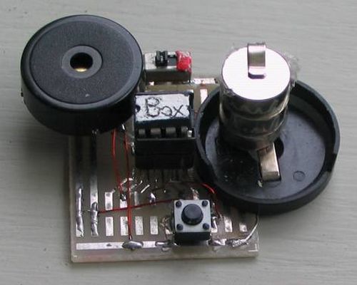
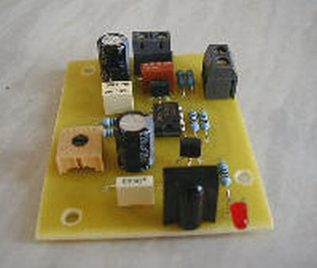
Ir LightDimmer is a small device (36*32mm) and can be easily mounted in electrical case where electrical wires terminate. Device works only with 220V/50Hz and only for resistive loads of 40W-400W. With Ir LightDimmer you can’t use inductive or capacity loads (only bulbs).
![]()
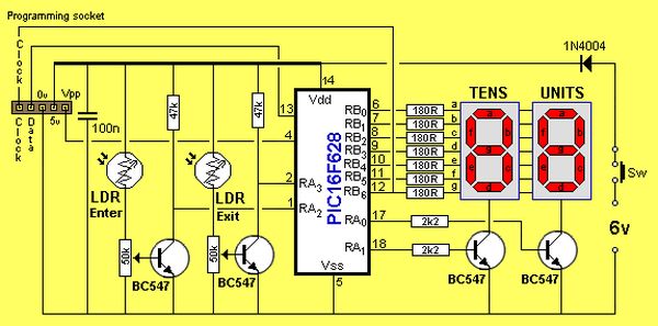
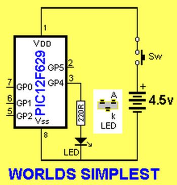
Device is based on PIC12F629 which is a small microchip microcontroller and therefore overall device is small and uses a few components. On circuit board you can find the IR-receiver, which in our case is TSOP1738, but you can use any other type of IR-receiver which has frequency of 38KHz. For output power stage you can use triac TIC206 or TIC216. For loads more than 150W you must add a heat sink on triac. The rest of parts are defined in schematic.
![]()
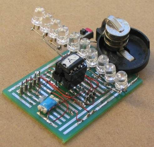
You must be careful when you connect IrLightDimmer to electrical wire, so you must break fuse switches of your lights. All connections must be like in my schematic, otherwise device will definitive burn out.
![]()
If you have IrLightDimmer mounted and connected and you want to change your lights, you must break fuse switches because there is risk of electric shock.
![]()
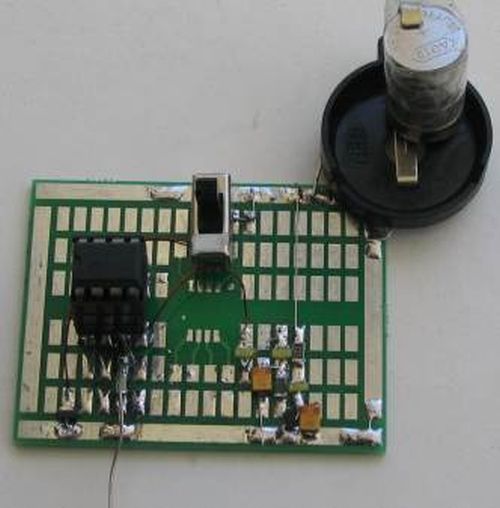
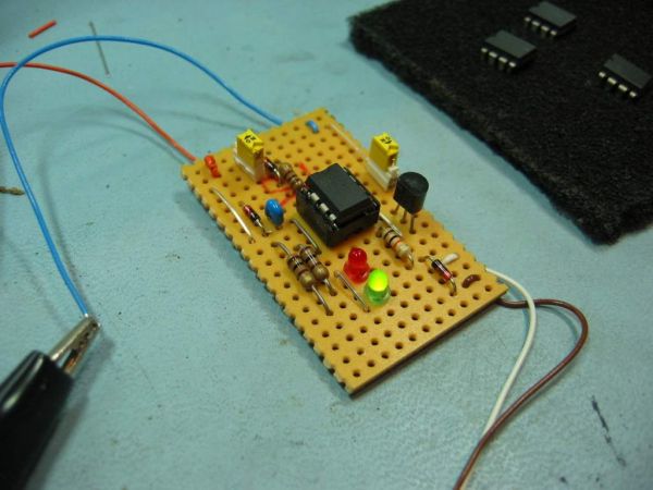
Dimming The Lights with remote controller, device Ir Light Dimmer, has got a new and simplest version. The most significant change is microcontroller PIC12F629 in Small-Outline Integrated Circuit (SOIC) package, TSOP2238 ir receiver instead of TSOP1738, and less components on circuit board.
So, at that way dimension of circuit board is shrink from 36 x 32 mm, to 27 x 21 mm.
All function of that version is the same like above described device Ir Light Dimmer v.1, so it’s no diference in software, only in schematic and in circuit board.
![]()
You must be careful when you connect IrLightDimmer to electrical wire, so you must break fuse switches of your lights. All connections must be like in my schematic, otherwise device will definitive burn out. experience in electrics, it’s better way t call skilled person to mount your Ir Light Dimmer.If you don’t have any ![]()
Schematic Ir Light Dimmer – PIC12F629 smd
![]()
Ir Light Dimmer v.1 works only with 220V/50Hz and only for resistive loads of 40W-400W. With Ir LightDimmer you can’t use inductive or capacity loads (only bulbs).
Source : Ir Light Dimmer v.1 adjusting lights with remote controller using PIC12F629


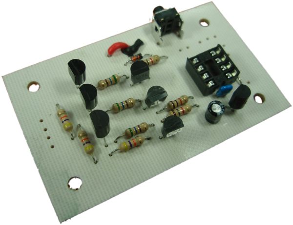


 circuit board